EasyManuals Logo

Hypertherm Powermax 125 Service Manual

Hypertherm Powermax 125
317 pages
To Next Page IconTo Next Page
To Previous Page IconTo Previous Page
Page #216 background imageLoading...
Page #216 background image
216 Powermax125 Service Manual 808070
9 Power Supply Component Replacement
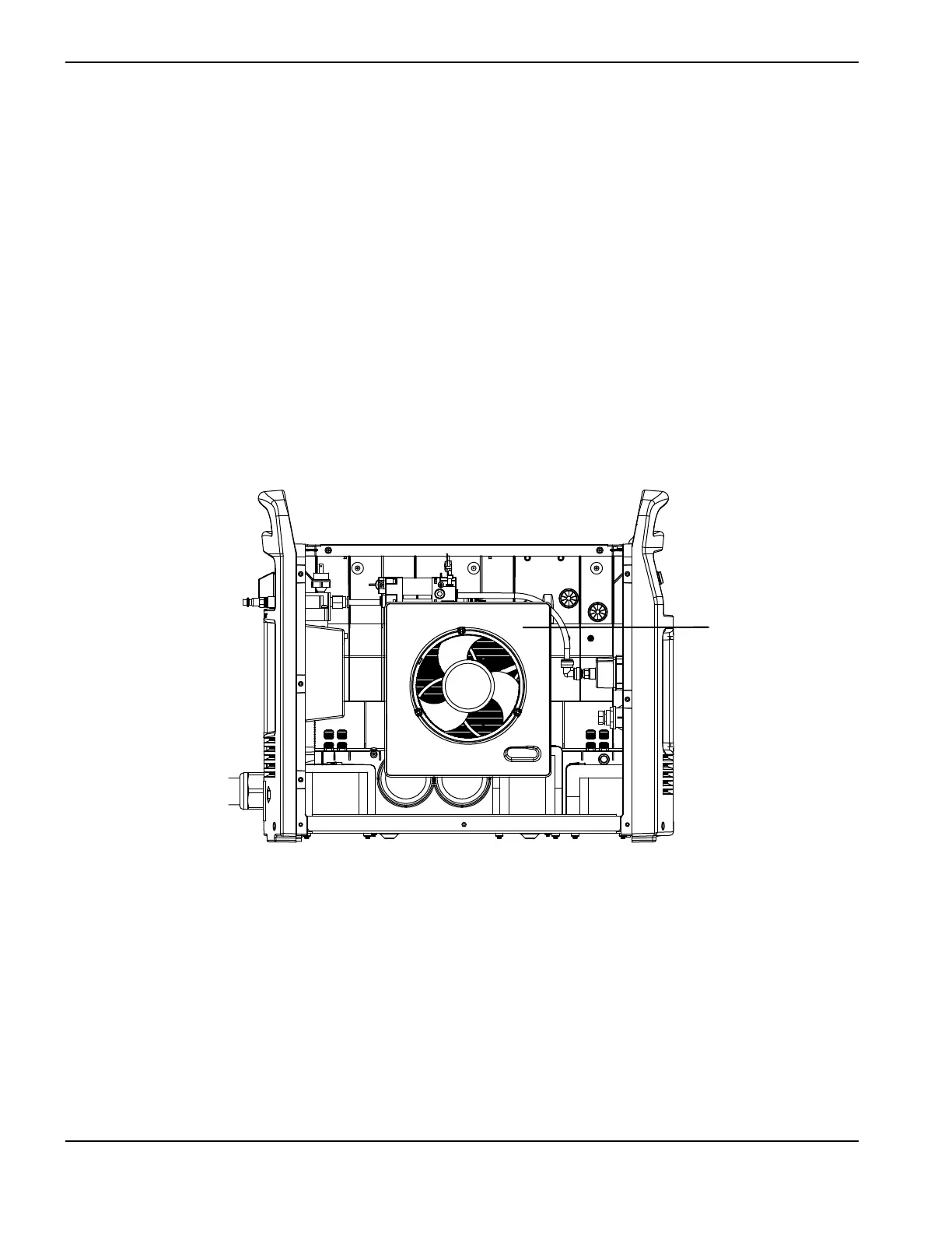
Replacing the fan shroud
Remove the fan shroud
1. Complete the following procedures:
a. See Disconnect the power and gas supply on page 166.
b. See Remove the power supply cover on page 172.
2. Grasp the fan shroud with two hands.
3. Pull the fan shroud straight off the fan housing.
Figure 77
Install the fan shroud
1. Align the 3 plastic posts on the back side of the fan shroud with the corresponding holes in the fan housing.
2. Push the fan shroud straight onto the fan housing.
3. Complete the following procedures:
a. See Install the power supply cover on page 172.
b. Reconnect the power and gas supply.
Kit number Description
228910 Kit: Powermax105/125 fan shroud
Fan shroud

Table of Contents

Other manuals for Hypertherm Powermax 125

Questions and Answers:

Question and Answer IconNeed help?

Do you have a question about the Hypertherm Powermax 125 and is the answer not in the manual?

Hypertherm Powermax 125 Specifications

General IconGeneral
Output Current30-125 A
Input Power15.2 kW
Open Circuit Voltage300 VDC
Gas SupplyClean, dry, oil-free air or nitrogen
Input Power Cable Length10 ft (3 m)
Rated Output Current125 A
Gas TypeAir or nitrogen
Cutting Capacity1-1/4 inch (32 mm)
Pierce Capacity1 inch (25 mm)
Input Voltage200-600 V, 3-PH
Duty Cycle100% @ 125 A
CertificationsCSA
Maximum Clean Cut Thickness1-1/4 inch (32 mm)
Cooling MethodFan-cooled
Torch OptionsHand

Related product manuals