EasyManuals Logo
Home>Hypertherm>Welding System>Powermax 125

Hypertherm Powermax 125 Service Manual

Hypertherm Powermax 125
317 pages
To Next Page IconTo Next Page
To Previous Page IconTo Previous Page
Page #215 background imageLoading...
Page #215 background image
Powermax125 Service Manual 808070 215
9 Power Supply Component Replacement
Figure 76 – Heatsink components
1
2
3
4
5
6
7
8
9
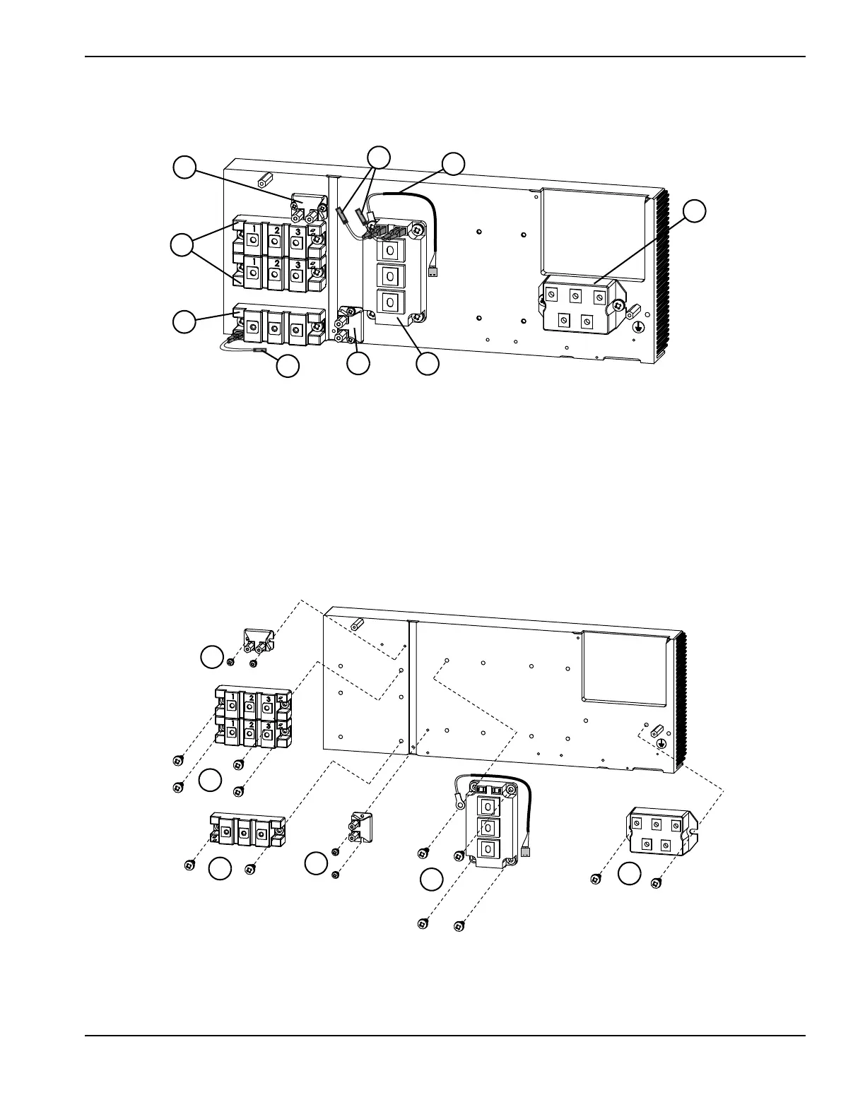
1 Snubber resistor 7.5 Ω 200 W (Kit 428137)
2 Output diode bridge (2) (Kit 428139)
3 Pilot arc IGBT (Kit 428138)
4 Pilot arc IGBT gate drive cable
5 Snubber resistor 15 Ω 200 W (Kit 228898)
6 Inverter IGBT module (Kit 428140)
7 Input diode bridge (Kit128746)
8 Thermal sensor (Kit 228805)
9 Inverter IGBT module gate drive cables
1
2
2
2
2
1
1 Torque to 17.3 kg-cm (15 inch-pounds). 2 Torque to 40 kg-cm (35 inch-pounds).

Table of Contents

Other manuals for Hypertherm Powermax 125

Questions and Answers:

Question and Answer IconNeed help?

Do you have a question about the Hypertherm Powermax 125 and is the answer not in the manual?

Hypertherm Powermax 125 Specifications

General IconGeneral
BrandHypertherm
ModelPowermax 125
CategoryWelding System
LanguageEnglish

Related product manuals