EasyManuals Logo

Hypertherm Powermax 125 Service Manual

Hypertherm Powermax 125
317 pages
To Next Page IconTo Next Page
To Previous Page IconTo Previous Page
Page #176 background imageLoading...
Page #176 background image
176 Powermax125 Service Manual 808070
9 Power Supply Component Replacement
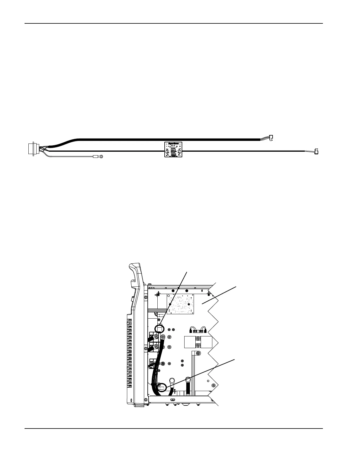
Replacing the machine interface cable with voltage divider board
Remove the machine interface cable with voltage divider board
Figure 43
1. Complete the following procedures:
a. See Disconnect the power and gas supply on page 166.
b. See Remove the power supply cover on page 172.
c. See Remove the component barrier on page 173.
2. Disconnect the cable connectors at J18 and J32.
Figure 44
Kit number Description
228884 Kit: Powermax105/125 machine interface cable, internal cable with voltage divider board
(CPC port)
J18
J32
Ground
J22
J27
WORK
LEAD
J26
_
RED
J18
ORG
J17
J32
J11
B
R
J28
RED
J32
J18
Power board

Table of Contents

Other manuals for Hypertherm Powermax 125

Questions and Answers:

Question and Answer IconNeed help?

Do you have a question about the Hypertherm Powermax 125 and is the answer not in the manual?

Hypertherm Powermax 125 Specifications

General IconGeneral
Output Current30-125 A
Input Power15.2 kW
Open Circuit Voltage300 VDC
Gas SupplyClean, dry, oil-free air or nitrogen
Input Power Cable Length10 ft (3 m)
Rated Output Current125 A
Gas TypeAir or nitrogen
Cutting Capacity1-1/4 inch (32 mm)
Pierce Capacity1 inch (25 mm)
Input Voltage200-600 V, 3-PH
Duty Cycle100% @ 125 A
CertificationsCSA
Maximum Clean Cut Thickness1-1/4 inch (32 mm)
Cooling MethodFan-cooled
Torch OptionsHand

Related product manuals