EasyManuals Logo

Hypertherm Powermax 125 Service Manual

Hypertherm Powermax 125
317 pages
To Next Page IconTo Next Page
To Previous Page IconTo Previous Page
Page #177 background imageLoading...
Page #177 background image
Powermax125 Service Manual 808070 177
9 Power Supply Component Replacement
3. Push the cables through the right grommet (see Figure 46 on page 178) from the power board side to the fan side of
the power supply.
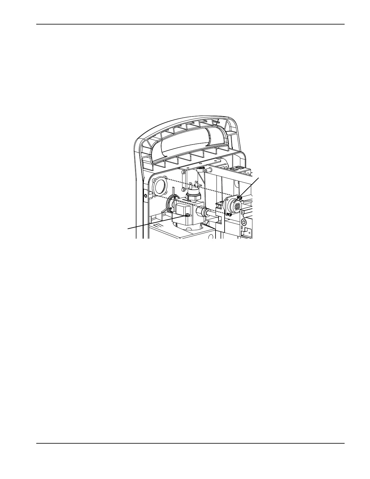
4. Remove the green/yellow ground wire screw from the gas filter housing. (See Figure 45.)
5. Remove the CPC port by removing the 2 screws.
Figure 45
6. Remove the 2 screws from the voltage divider board and remove the voltage divider board and attached cables. (See
Figure 46 on page 178.)
CPC port
Ground wire screw

Table of Contents

Other manuals for Hypertherm Powermax 125

Questions and Answers:

Question and Answer IconNeed help?

Do you have a question about the Hypertherm Powermax 125 and is the answer not in the manual?

Hypertherm Powermax 125 Specifications

General IconGeneral
Output Current30-125 A
Input Power15.2 kW
Open Circuit Voltage300 VDC
Gas SupplyClean, dry, oil-free air or nitrogen
Input Power Cable Length10 ft (3 m)
Rated Output Current125 A
Gas TypeAir or nitrogen
Cutting Capacity1-1/4 inch (32 mm)
Pierce Capacity1 inch (25 mm)
Input Voltage200-600 V, 3-PH
Duty Cycle100% @ 125 A
CertificationsCSA
Maximum Clean Cut Thickness1-1/4 inch (32 mm)
Cooling MethodFan-cooled
Torch OptionsHand

Related product manuals