178 Powermax125 Service Manual 808070
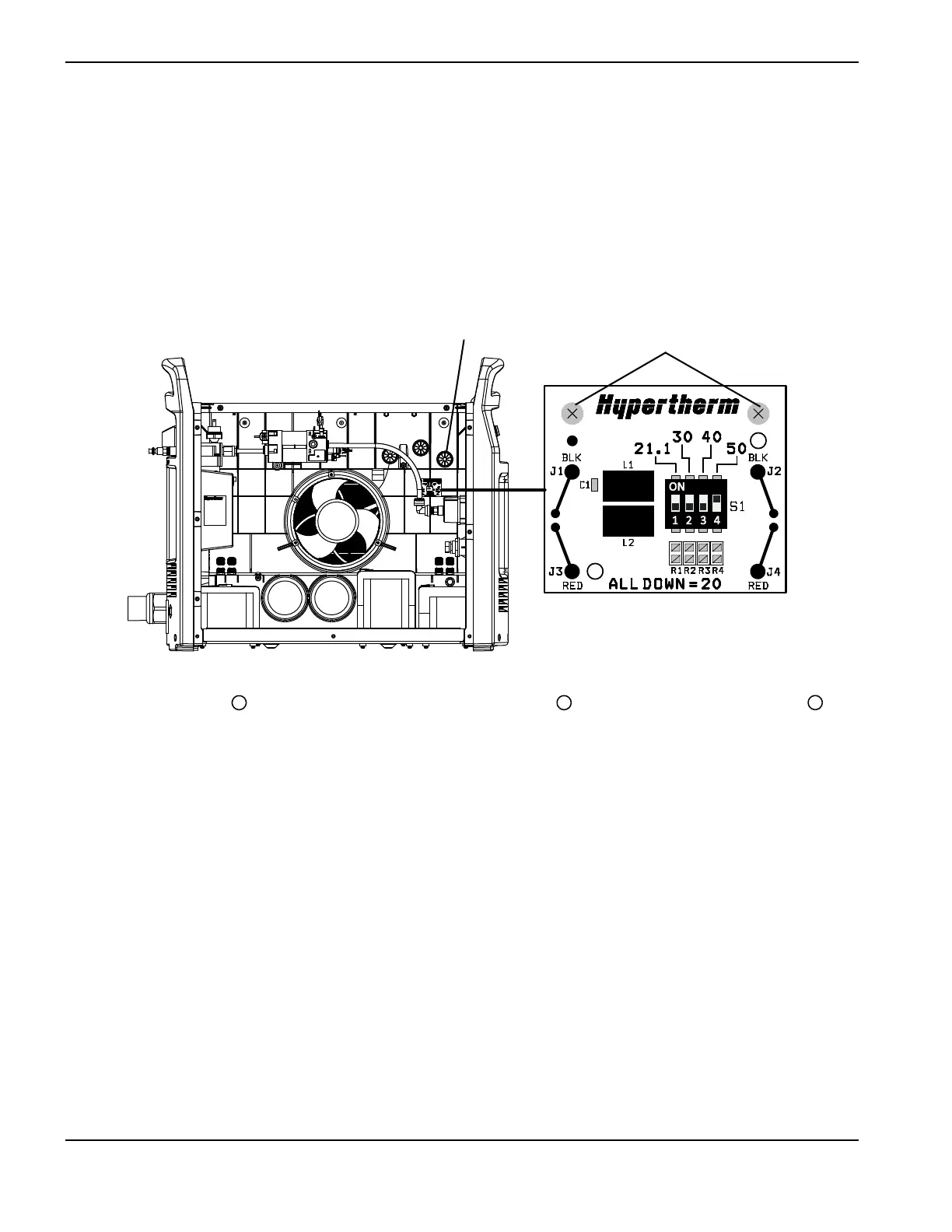
9 – Power Supply Component Replacement
Install the machine interface cable with voltage divider board
1. Verify the power supply is turned OFF, the power is disconnected, and the gas supply is disconnected.
2. Remove the power supply cover and the component barrier, if they are not already.
3. Install the voltage divider board to the right of the power supply fan by tightening 2 of the supplied screws to
11.5 kg-cm (10 inch-pounds).
Figure 46
4. Route the CPC port and attached cables above the solenoid valve and over to the CPC port opening on
the rear panel of the power supply. (See Figure 47 on page 179.)
5. Insert the CPC port into the CPC port opening from inside the power supply. Be sure to position the port with the
green/yellow ground wire at the bottom of the port.
6. Attach the CPC port by tightening 2 of the supplied screws to 11.5 kg-cm (10 inch-pounds). Two screws are
sufficient when inserted in opposite corners of the CPC port.