Powermax125 Service Manual 808070 179
9 – Power Supply Component Replacement
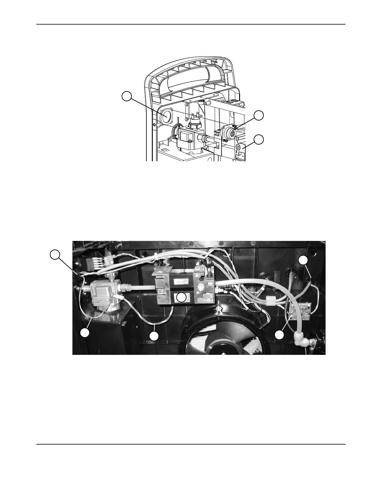
Figure 47
7. Attach the green/yellow ground wire (from the CPC port) to the gas filter housing using the same screw that secures
the large ground wire connected to the center panel. Tighten the ground wire screw to 17.3 kg-cm (15 inch-pounds).
8. Route the 2 cables through the right grommet one at a time and down the left side of the power board.
Figure 48
4 CPC port
5 CPC port ground wire
6 Large ground wire from center panel
7 Solenoid valve
8 Voltage divider board
9 Right grommet