EasyManuals Logo

Hypertherm Powermax 125 Service Manual

Hypertherm Powermax 125
317 pages
To Next Page IconTo Next Page
To Previous Page IconTo Previous Page
Page #180 background imageLoading...
Page #180 background image
180 Powermax125 Service Manual 808070
9 Power Supply Component Replacement
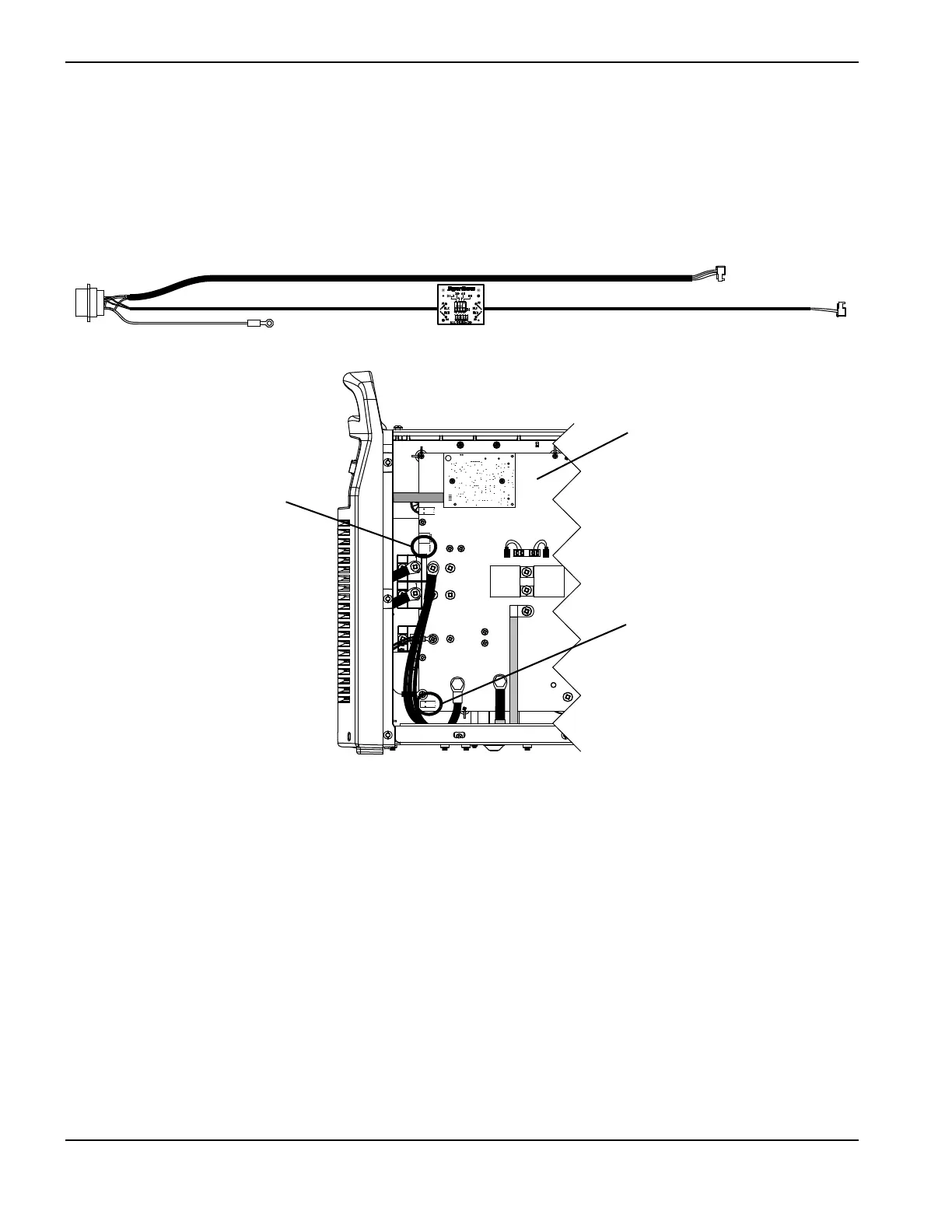
9. Route the larger diameter cable to J18. At J18 align the red wire in the cable connector with the “RED” that is printed
on the power board, and push the cable connector into the power board connector.
10. Route the smaller diameter cable to J32. At J32 align the red wire in the cable connector with the “RED” that is
printed on the power board, and push the cable connector into the power board connector.
Figure 49
11. From the fan side of the power supply, secure both cables in the cable clip attached to the center panel under the left
grommet.
12. Set the voltage divider board. (See Set the voltage divider board on page 181.)
13. Complete the following procedures:
a. See Install the component barrier on page 173.
b. See Install the power supply cover on page 172.
c. Reconnect the power and gas supply.
J22
J27
WORK
LEAD
J26
_
RED
J18
ORG
J17
J32
J11
B
R
J28
RED
J18
J32
Ground
J32
J18
Power board

Table of Contents

Other manuals for Hypertherm Powermax 125

Questions and Answers:

Question and Answer IconNeed help?

Do you have a question about the Hypertherm Powermax 125 and is the answer not in the manual?

Hypertherm Powermax 125 Specifications

General IconGeneral
Output Current30-125 A
Input Power15.2 kW
Open Circuit Voltage300 VDC
Gas SupplyClean, dry, oil-free air or nitrogen
Input Power Cable Length10 ft (3 m)
Rated Output Current125 A
Gas TypeAir or nitrogen
Cutting Capacity1-1/4 inch (32 mm)
Pierce Capacity1 inch (25 mm)
Input Voltage200-600 V, 3-PH
Duty Cycle100% @ 125 A
CertificationsCSA
Maximum Clean Cut Thickness1-1/4 inch (32 mm)
Cooling MethodFan-cooled
Torch OptionsHand

Related product manuals