EasyManuals Logo

Hypertherm Powermax 125 Service Manual

Hypertherm Powermax 125
317 pages
To Next Page IconTo Next Page
To Previous Page IconTo Previous Page
Page #223 background imageLoading...
Page #223 background image
Powermax125 Service Manual 808070 223
9 Power Supply Component Replacement
Replacing the gas filter assembly
Remove the gas filter assembly
1. Complete the following procedures:
a. See Disconnect the power and gas supply on page 166.
b. See Remove the power supply cover on page 172.
c. See Remove the end panel bracket on page 174.
d. See Remove the gas filter element on page 167.
2. Disconnect the 2 wire terminals from the top of the pressure switch.
3. Remove the screw securing the 2 ground wires to the gas filter housing.
4. Push in the plastic ring on the push-to-connect fitting. Gently pull the top of the rear panel away from the power
supply until the gas tube pulls out of the push-to-connect fitting.
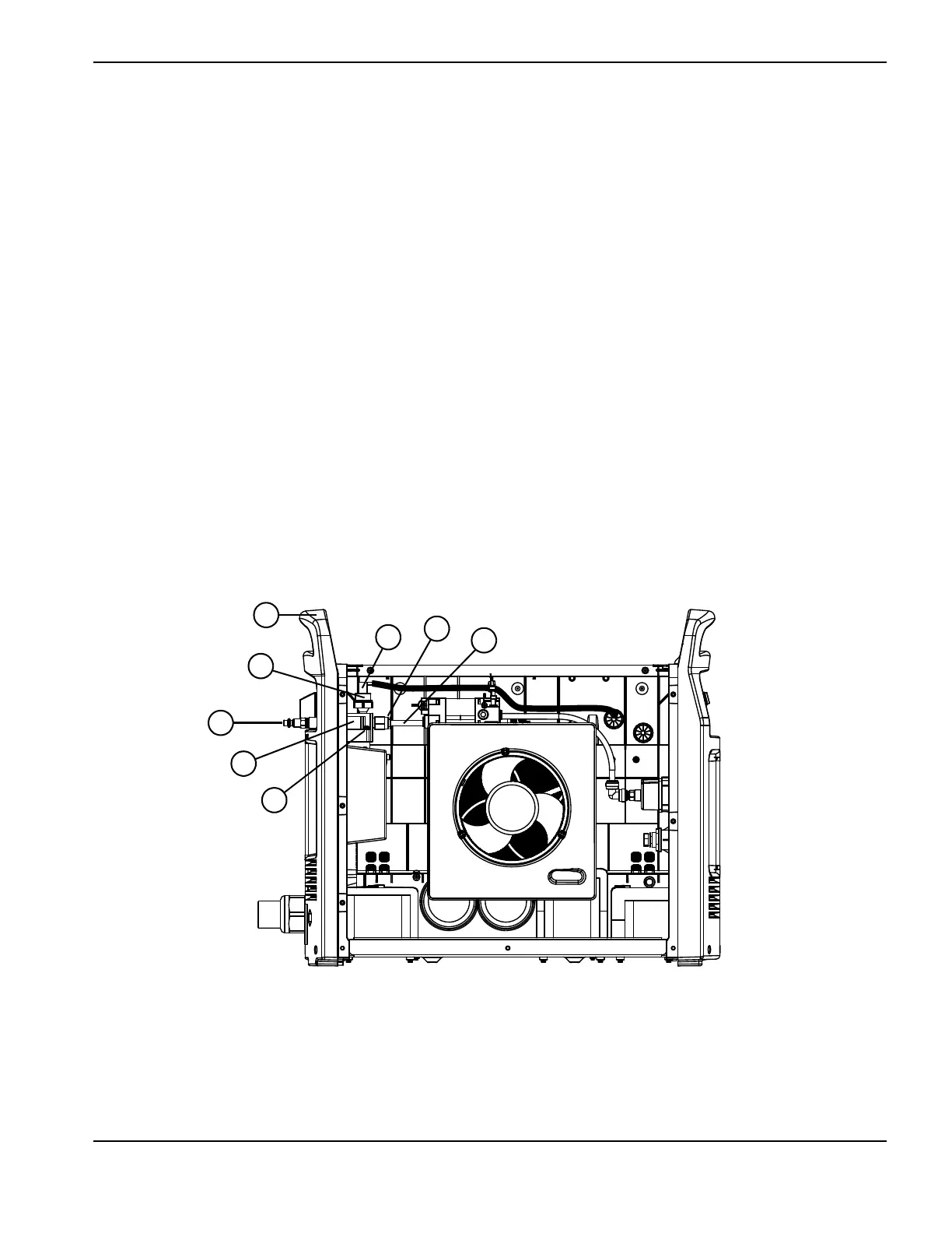
Figure 82
Kit number Description
228685 Kit: Powermax65/85/105/125 gas filter assembly
1
2
3
4
5
6
7
8
1 Rear panel
2 Pressure switch
3 Gas fitting
4 Gas filter housing
5 Ground wire screw
6 Gas tube
7 Push-to-connect fitting
8 Wire terminals

Table of Contents

Other manuals for Hypertherm Powermax 125

Questions and Answers:

Question and Answer IconNeed help?

Do you have a question about the Hypertherm Powermax 125 and is the answer not in the manual?

Hypertherm Powermax 125 Specifications

General IconGeneral
Output Current30-125 A
Input Power15.2 kW
Open Circuit Voltage300 VDC
Gas SupplyClean, dry, oil-free air or nitrogen
Input Power Cable Length10 ft (3 m)
Rated Output Current125 A
Gas TypeAir or nitrogen
Cutting Capacity1-1/4 inch (32 mm)
Pierce Capacity1 inch (25 mm)
Input Voltage200-600 V, 3-PH
Duty Cycle100% @ 125 A
CertificationsCSA
Maximum Clean Cut Thickness1-1/4 inch (32 mm)
Cooling MethodFan-cooled
Torch OptionsHand

Related product manuals