Powermax125 Service Manual 808070 171
9 – Power Supply Component Replacement
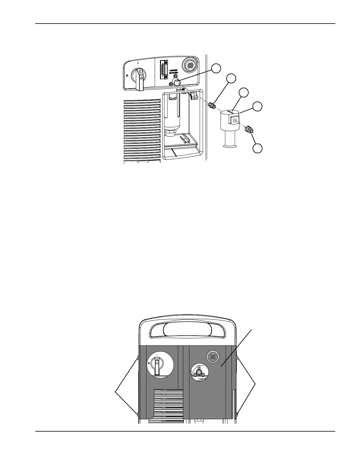
Figure 37
6. Remove the upper 2 screws from each side of the power supply (Figure 38).
7. Place the filter cover over the filter on the rear of the power supply, aligning the screw holes with the holes in the
power supply cover.
8. Install the 4 screws provided in the kit through the filter cover and power supply cover. Tighten the screws to
23 kg-cm (20 inch-pounds).
9. Reconnect the power and gas supply.
Figure 38
1 Gas inlet fitting
2 Bracket
3 Adapter fitting
4 Arrow pointing to power supply
5 Filter
 Loading...


