Powermax125 Service Manual 808070 239
9 – Power Supply Component Replacement
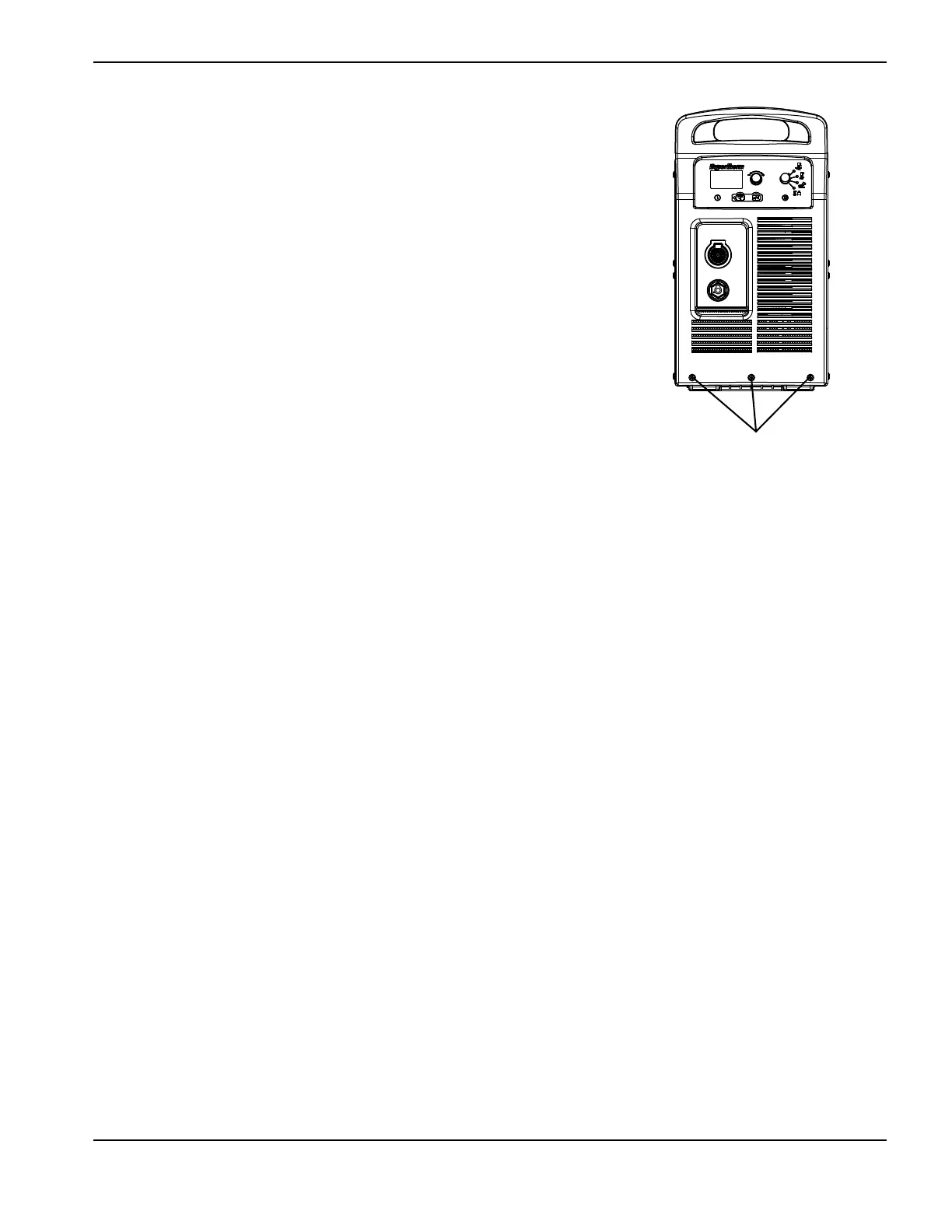
4. Remove the 3 mounting screws from the bottom of the
front panel.
5. From the fan side of the power supply, disconnect the 90°
push-to-connect fitting by pushing in the plastic ring
(closest to the brass nut) and pulling the fitting away from
the nut. (See Figure 96 on page 240.)
6. Disconnect the electrode wire and short inductor wires by
removing the brass nut that secures the ring terminal to
the quick disconnect housing.
The electrode wire and short inductor wires are
captured in the same wire connector.
7. Pull the electrode wire through the protective sheathing
that passes through the center panel.
8. Carefully slide the front panel a short distance away from
the base of the power supply.
9. Remove the 2 mounting screws in the base of the output inductor.
10. Lift the output inductor out of the power supply while guiding the long inductor wires through the opening in the
bottom of the center panel.
Front panel mounting screws