EasyManuals Logo

Hypertherm Powermax 125 Service Manual

Hypertherm Powermax 125
317 pages
To Next Page IconTo Next Page
To Previous Page IconTo Previous Page
Page #237 background imageLoading...
Page #237 background image
Powermax125 Service Manual 808070 237
9 Power Supply Component Replacement
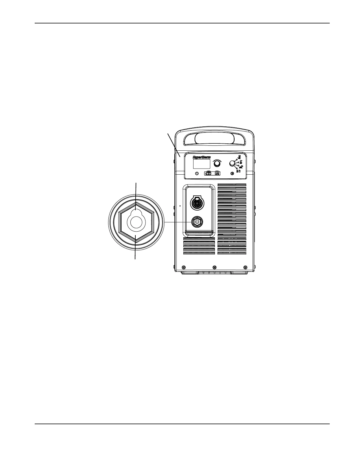
5. Push the threaded end of the new work lead receptacle into the opening in the front panel, with the keyway facing up,
until fully seated. (See Figure 94.)
6. Place the lock washer over the work lead receptacle inside the power supply.
7. Tighten the nut onto the work lead receptacle.
8. Secure the work cable to the work lead receptacle by tightening the bolt.
Figure 94
9. Complete the following procedures:
a. See Install the fan shroud on page 216.
b. See Install the power supply cover on page 172.
c. Reconnect the power and gas supply.
Front panel
Work lead receptacle
Keyway up

Table of Contents

Other manuals for Hypertherm Powermax 125

Questions and Answers:

Question and Answer IconNeed help?

Do you have a question about the Hypertherm Powermax 125 and is the answer not in the manual?

Hypertherm Powermax 125 Specifications

General IconGeneral
Output Current30-125 A
Input Power15.2 kW
Open Circuit Voltage300 VDC
Gas SupplyClean, dry, oil-free air or nitrogen
Input Power Cable Length10 ft (3 m)
Rated Output Current125 A
Gas TypeAir or nitrogen
Cutting Capacity1-1/4 inch (32 mm)
Pierce Capacity1 inch (25 mm)
Input Voltage200-600 V, 3-PH
Duty Cycle100% @ 125 A
CertificationsCSA
Maximum Clean Cut Thickness1-1/4 inch (32 mm)
Cooling MethodFan-cooled
Torch OptionsHand

Related product manuals