140 Powermax125 Service Manual 808070
8 – Troubleshooting and System Tests
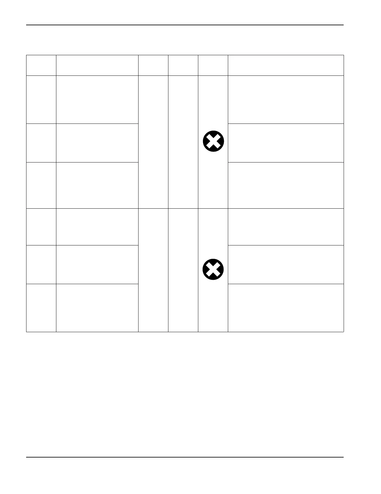
3-20-1 Dump valve
Indicates that the dump valve
is not connected.
On On
• Check the associated wiring.
•Perform Test 9 – Electronic regulator
on page 162.
• If necessary, replace the electronic
regulator (228687).
3-20-2 Valve ID The DSP does not recognize the
electronic regulator.
• Check the harness from the regulator
to J6.
3-20-3 Electronic regulator is
disconnected
The electronic regulator is
not drawing current.
• Inspect the associated wiring,
particularly the 7-pin connector at J6
on the power board.
• If necessary, replace the electronic
regulator (228687).
3-41-0 Drive fault
On On
If an activation signal is sent to a device
and the device does not activate (machine
motion relay or in-rush relay for example)
this fault will occur.
3-42-0 5 or 24 VDC fault The 5 or 24 VDC supply from the flyback
circuit is out of range.
Perform Test 5 – Flyback circuit (DC
minor voltages) on page 156.
3-42-1 Driver voltage fault The 18 VDC supply from the flyback
circuit is out of range.
• Replace the power board.
• Check the inverter IGBT module and
replace if necessary.
3-nn-n
Fault
code
Description
Power
LED
Fault
LED
Fault
icon
Solutions