EasyManuals Logo

Hypertherm Powermax 125 Service Manual

Hypertherm Powermax 125
317 pages
To Next Page IconTo Next Page
To Previous Page IconTo Previous Page
Page #159 background imageLoading...
Page #159 background image
Powermax125 Service Manual 808070 159
8 Troubleshooting and System Tests
If the resistance is still greater than 100 Ω, measure the resistance in the torch between the pilot arc wires (pin 1
or 2) and negative arc power (the center connection).
If the resistance is still too high, replace the torch and lead.
The retaining cap should be snug but not overtightened.
All values are ±50%. However, this range is intended only for reference. Resistance
values can vary widely depending on the type of multimeter and the polarity used to
measure the readings.
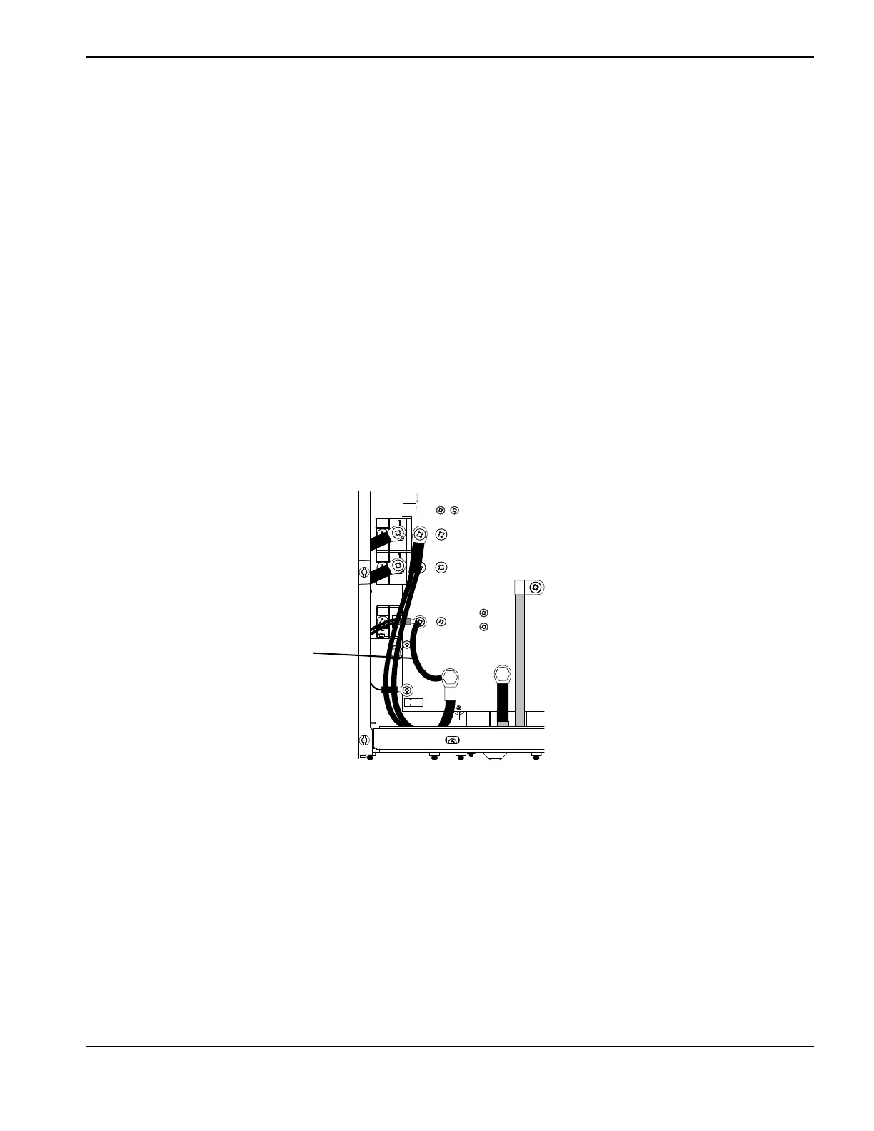
Check the function of the pilot arc IGBT:
Turn the machine OFF and disconnect the power.
Install a jumper wire (at least 8 AWG) from the work lead (J27) to the pilot arc IGBT (dual black wires).
Reconnect the power and turn on the machine.
Attempt to fire the torch.
If the torch fires, replace the pilot arc IGBT.
Figure 28
J27
WORK
LEAD
J26
RED
J18
ORG
J17
J32
J28
RED
Install a test jumper here

Table of Contents

Other manuals for Hypertherm Powermax 125

Questions and Answers:

Question and Answer IconNeed help?

Do you have a question about the Hypertherm Powermax 125 and is the answer not in the manual?

Hypertherm Powermax 125 Specifications

General IconGeneral
Output Current30-125 A
Input Power15.2 kW
Open Circuit Voltage300 VDC
Gas SupplyClean, dry, oil-free air or nitrogen
Input Power Cable Length10 ft (3 m)
Rated Output Current125 A
Gas TypeAir or nitrogen
Cutting Capacity1-1/4 inch (32 mm)
Pierce Capacity1 inch (25 mm)
Input Voltage200-600 V, 3-PH
Duty Cycle100% @ 125 A
CertificationsCSA
Maximum Clean Cut Thickness1-1/4 inch (32 mm)
Cooling MethodFan-cooled
Torch OptionsHand

Related product manuals