202 Powermax125 Service Manual 808070
9 – Power Supply Component Replacement
4. Align the inside flat edge of the operating mode switch knob (with the white line) with the flat side of the control
board post, and push the knob straight onto the post.
5. Align the inside flat edge of the current adjustment knob with the flat side of the control board post, and push the
knob straight onto the post.
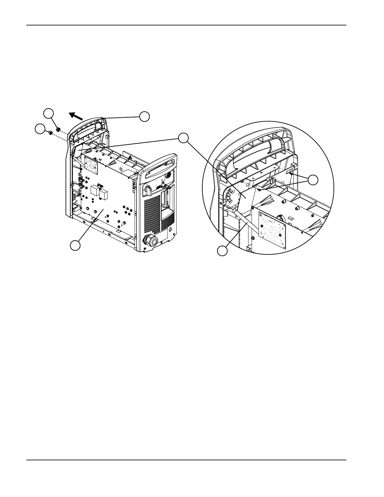
Figure 71
6. Complete the following procedures:
a. See Install the end panel bracket on page 175.
b. See Install the component barrier on page 173.
c. See Install the power supply cover on page 172.
d. Reconnect the power and gas supply.
1 Current adjustment knob
2 Operating mode knob
3 Power board
4 Ribbon cable
5 Top mounting screws
6 Control board
7 Top of front panel