204 Powermax125 Service Manual 808070
9 – Power Supply Component Replacement
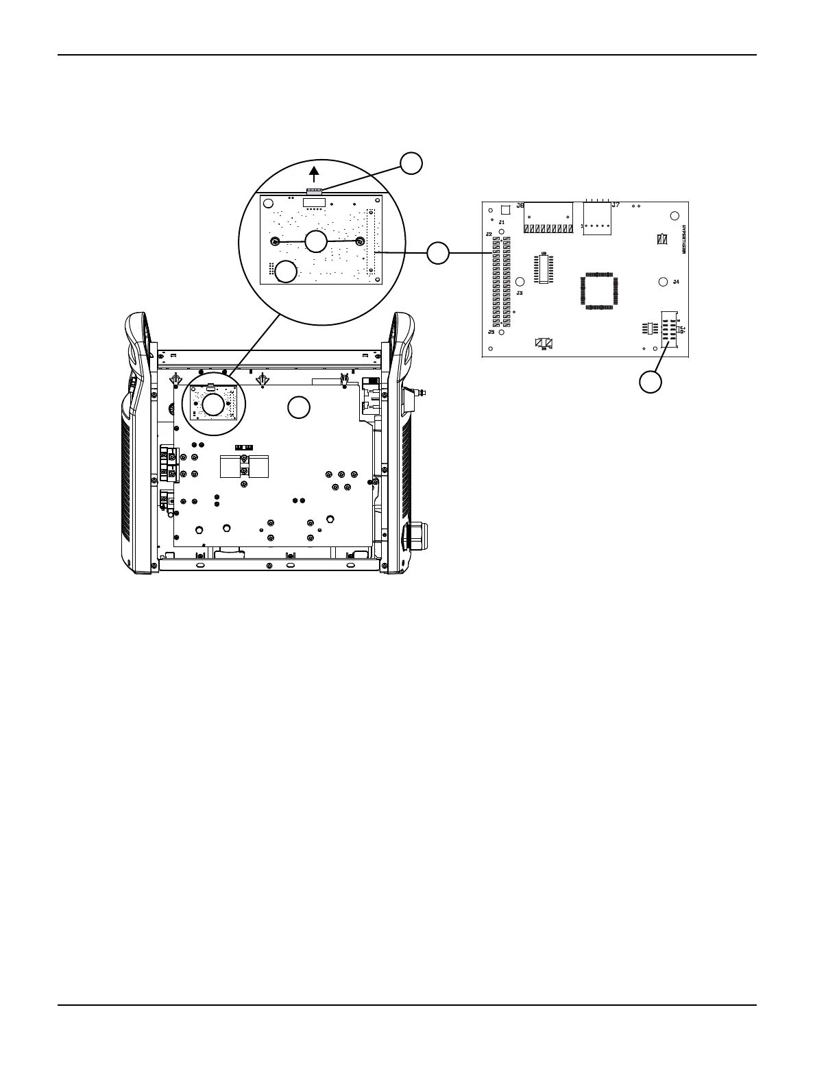
Figure 72
6. Complete the following procedures:
a. See Install the component barrier on page 173.
b. See Install the power supply cover on page 172.
c. Reconnect the power and gas supply.
1
2
3
4
5
6
3
DSP front view
DSP back view
1 DSP connector (J7)
2 DSP connector screws (2)
3 DSP board
4 Connector pins
5 Power board
6 J6 connector