230 Powermax125 Service Manual 808070
9 – Power Supply Component Replacement
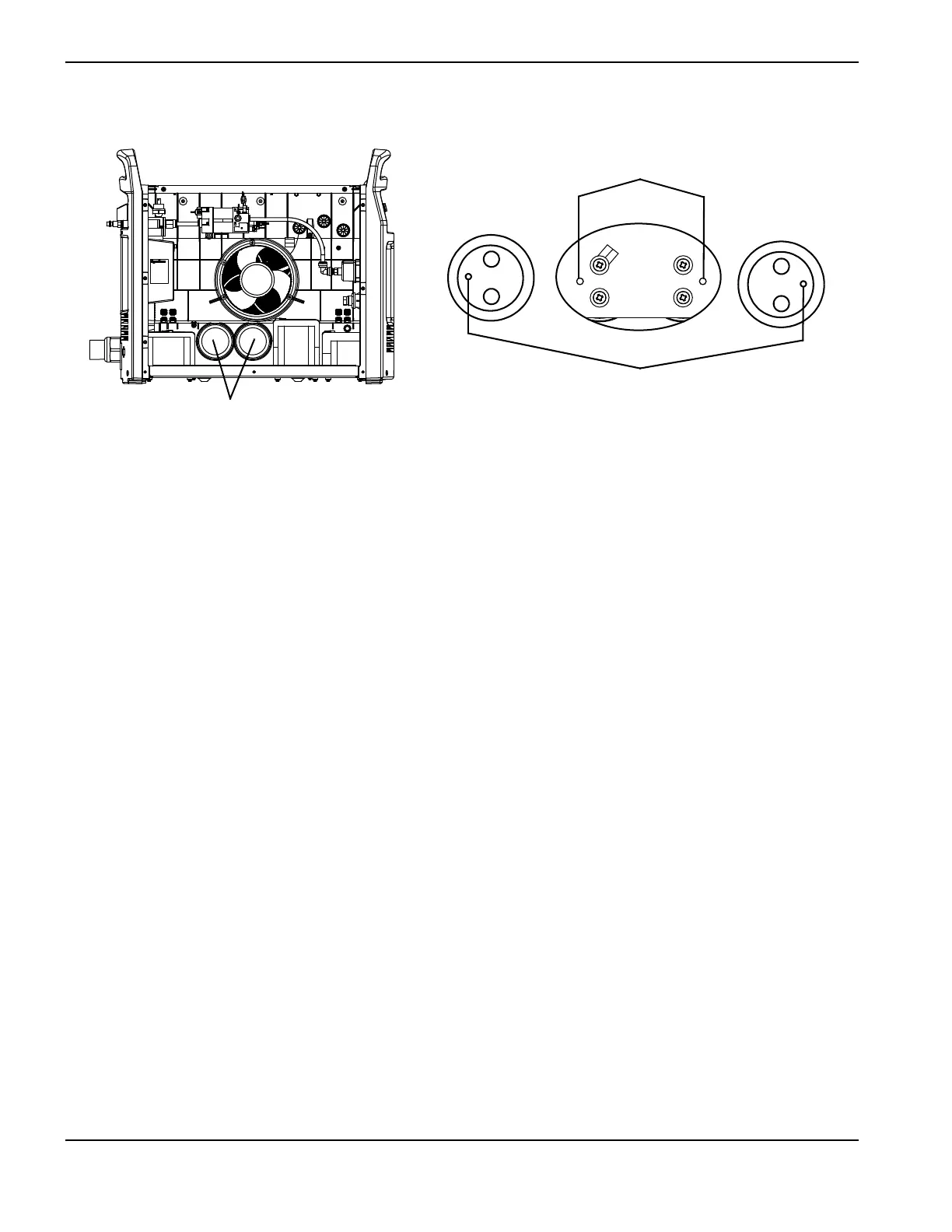
Figure 88
7. Complete the following procedures:
a. See Install the fan shroud on page 216.
b. See Install the component barrier on page 173.
c. See Install the power supply cover on page 172.
d. Reconnect the power and gas supply.
+
+
Bulk capacitor polarity dots
Bulk capacitors
Power board viewing holes