260 Powermax125 Service Manual 808070
9 – Power Supply Component Replacement
13. Remove the handle screw that secures the power switch handle to the post.
14. Pull the power switch handle straight off the post. If the white plastic cap does not come off with the handle, pull the
cap off the post as well.
15. Pry up the right edge of the power switch label. If the optional RS-485 connector is not installed, the label extends to
the right side of the inlet gas fitting.
16. Peel off the entire label to expose the 4 mounting screws that secure the power switch to the rear panel.
17 . Remove the power switch from the rear panel by removing the 4 mounting screws.
18. Remove the 3 mounting screws from the base of the rear panel, if they are not already removed.
19. Remove the rear panel.
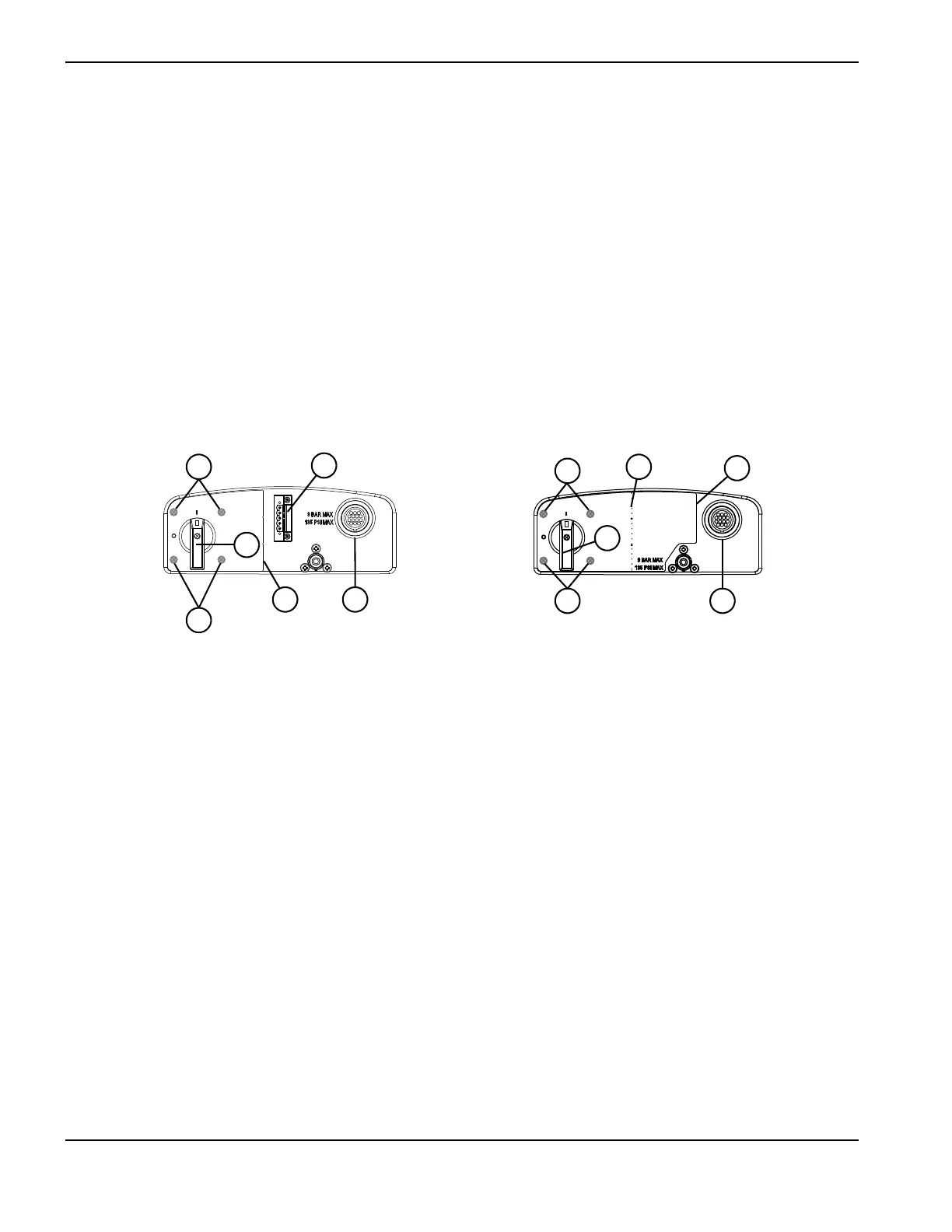
Figure 113 – Rear panel with and without the RS-485 connector installed
1 Power switch screws (4) (behind label)
2 Power switch handle
3 Right edge of label
4 CNC interface connector
5 Label perforation
6 Optional RS-485 connector