EasyManuals Logo

Hypertherm Powermax 125 Service Manual

Hypertherm Powermax 125
317 pages
To Next Page IconTo Next Page
To Previous Page IconTo Previous Page
Page #34 background imageLoading...
Page #34 background image
34 Powermax125 Service Manual 808070
2 Power Supply Setup
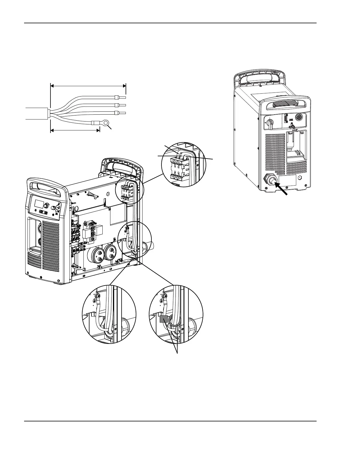
Strip and prepare the power cord wires as shown in the following figure. For CE units, ferrite cores are installed around
the three power wires and around the ground wire; CSA and CCC models do not have ferrite cores on the power cord
wires.
CCC models do not ship with a power cord. To maintain CE certification, install power
cord kit 228886.
L1
L2
L3
L1
L2
L3
Ground
419 mm (16.5 inches)
203 mm
(8 inches)
6mm (0.25inch)
Route lead through strain relief
and tighten
CSA/CCC power cords
(no ferrite cores)
CE power cord
(ferrite cores on power
wires and ground wire)

Table of Contents

Other manuals for Hypertherm Powermax 125

Questions and Answers:

Question and Answer IconNeed help?

Do you have a question about the Hypertherm Powermax 125 and is the answer not in the manual?

Hypertherm Powermax 125 Specifications

General IconGeneral
Output Current30-125 A
Input Power15.2 kW
Open Circuit Voltage300 VDC
Gas SupplyClean, dry, oil-free air or nitrogen
Input Power Cable Length10 ft (3 m)
Rated Output Current125 A
Gas TypeAir or nitrogen
Cutting Capacity1-1/4 inch (32 mm)
Pierce Capacity1 inch (25 mm)
Input Voltage200-600 V, 3-PH
Duty Cycle100% @ 125 A
CertificationsCSA
Maximum Clean Cut Thickness1-1/4 inch (32 mm)
Cooling MethodFan-cooled
Torch OptionsHand

Related product manuals