Home
IBM
Printer
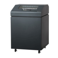
Infoprint 6500-v05
IBM Infoprint 6500-v05
544 pages
Manual
To Next Page
To Next Page
To Previous Page
To Previous Page
Loading...
257
Exhaust F
an (in cabine
t models)
Magnetic
Pick-up Uni
t (MPU)
•
Shuttle M
otor Intermedia
te Cable
•
Hammer Bank
Power and Logi
c Intermediate
Cables
•
Operator
Panel Assemb
ly Intermed
iate Cable
•
Power Stacker Logic and Po
wer (Interm
ediate) Cabl
es
256
258
Table of Contents
Main Page
Table of Contents
3
Energy Star
10
Notices
10
Communication Statements
12
European Union (EC) Electromagnetic Compatibility Directives
16
Electrical Safety
17
Lightning Safety
17
Safety and Notices
17
Trademarks and Service Marks
19
Safety Inspection
21
Preparation
21
Prepare the Printer for Inspection
21
Inspect Mechanical Parts
22
Inspect Electrical Parts
23
Preface
26
About this Manual
26
Printing Conventions in this Manual
27
Related Documents
28
About the Printer
29
The IBM Infoprint 6500 Printer Family
29
How to Identify the Printer
30
Printer Configuration Code
31
Forms Handling
32
Important Maintenance Notes
33
Controls and Indicators
34
Electrical Controls: Figure 5
34
Mechanical Controls: Figure 6
37
1 Diagnosing Problems
39
Introduction
39
Troubleshooting at a Glance
39
Start of Call
40
How to Troubleshoot
41
Troubleshooting Display Messages
42
Display Messages
42
Communications Failures
48
Operator Panel Message 301 - 305
138
Troubleshooting Other Symptoms
170
Communication Problems
171
Device Handshaking
174
The Printer Interface
174
General Symptom List
176
Operator Panel
180
Power Stacker
187
Print Quality
193
Printer Operation
200
2 Diagnostics
212
Contents
212
Operator Print Tests
213
Selecting and Running Tests
215
Customer Engineer (CE) Tests
216
Selecting and Running CE Tests
220
Activating the Boot Diagnostic Menu
221
Boot Diagnostics Menu
221
Exiting the Boot Diagnostic Menu
221
Hex Code Printout
224
Printer Information Menu
226
Displaying Printer Information
227
Soft Vs. Hard Reset
228
Soft Reset
228
Hard Reset ("Cycle Power")
228
Controller Board Status Leds at Power up
229
Troubleshooting a New Installation
230
Printer Configuration
230
Documentation
230
Ribbonminder
231
Ribbonminder Operation
231
Ribbon Action
233
The Ribbon Log
235
Downloading Microcode from IBM First
236
Clear NVRAM
237
Loading Flash Memory
238
Loading through the Serial or Parallel Port
239
Loading through the Network Interface Card (NIC)
248
Reprogramming the Security Key
250
Shuttle Electrical Shorts Test
252
Hammer Bank Power Cable Shorts Test
253
Cable Shorts Test
254
Main Wire Harness Test Diagnostic
256
Power Supply Operational Check
258
Locations
262
Locations of Components and Assemblies
262
4 Circuit Diagrams, Circuit Boards, Cables, and Switches
264
Contents
264
Interconnection Diagram
266
Power Distribution Diagram
267
Main Wire Harness Test Tables, PSA3 Controller Board
268
PSA3 Controller
269
Power Supply: 6500-V05, -V5P, -V10, and I1P
277
Power Supply: 6500-V15
278
Power Supply: 6500-V20
279
IBM Coax/Twinax Expansion Board for PSA3 Controllers
280
Surestak Power Stacker PCBA
281
Cable Routing, Cabinet Model
282
Cable Routing, Pedestal Model
283
Cable Assembly, Centronics I/O
284
Cable Assembly, Centronics/Dataproducts Adapter
285
Cable Assembly, +5V Remote Power
286
Cable Assembly, Twinax Auto-Termination
287
Cable Extension, Smart-T
288
Cable Assembly, PS I/O, 2000
289
Cable Assembly, AC In, Power Supply
290
Cable Assembly, AC Power Input
291
Cable Assembly, Card Cage Fan
292
Chapter 4 Contents
292
Cable Assembly, Operator Panel
293
Cable Assembly, Exhaust Fan
294
Cable Assembly, Hammer Bank Logic
295
Cable Assembly, Hammer Bank Power
296
Cable Assembly, Dual Hammer Bank Power
297
Cable Assembly, MPU
298
Cable Assembly, Ribbon Guide
299
Cable Assembly, Ribbon Motor, Extension
300
Cable Assembly, Shuttle Motor Drive
301
Frame Cable, Power Stacker
302
Logic Cable, Power Stacker
303
Power Cable, Power Stacker
304
Vertical Rail Cable, Power Stacker
305
Elevator I/O Cable, Power Stacker
306
Fan Assembly, Hammer Bank
307
Magnetic Pickup (MPU) Assembly
308
Switch Assembly, Paper Detector
309
Switch Assembly, Platen Interlock
310
Removals and Adjustments
311
About this Chapter
311
Tools and Materials
311
Preparing the Printer for Maintenance
313
Restoring the Printer to Operation
314
Removal and Replacement Procedures
315
List of Procedures
315
Belt, Paper Feed Timing
317
Belt, Platen Open
318
Circuit Board: PSA3 Controller
319
Circuit Board: Power Supply
321
Circuit Breaker
322
Connector Shells
323
Cover Assembly, Hammer Bank / Ribbon Mask
325
Cover Assembly, Shuttle
326
Cover Assembly, Top, Pedestal Model
327
Dashpot
328
Ethernet Interface Assembly
329
Fan Assembly, Cabinet Exhaust
330
Fan Assembly, Card Cage
331
Fan Assembly, Hammer Bank
332
Hammer Spring Assembly
333
IBM Coax/Twinax Expansion Board
337
Magnetic Pick-Up (MPU) Assembly
338
Memory Modules and Security Key
339
Security Key
339
Motor Assembly, Paper Feed
342
Chapter 5 Removal and Replacement Procedures
344
Motor Assembly, Platen Open
344
Motor Assembly, Ribbon Drive
346
Operator Panel Assembly
347
Paper Guide Assembly
348
Paper Ironer
349
Platen
350
Platen Stop Assembly (and Forms Thickness Lever)
354
Resistors, Terminating
355
Controller Board
356
Ribbon Guide Assembly (L/R)
357
Ribbonminder Sensor
358
Shaft, Splined
359
Shaft, Support
361
Shuttle Frame Assembly
362
Spring, Extension, Hammer Bank
364
Switch Assembly, Paper Detector
365
Switch Assembly, Platen Interlock
366
Tractor (L/R)
367
Adjustment Procedures
368
List of Adjustments
368
Belt, Paper Feed Timing, Adjustment
369
Belt, Platen Open, Adjustment
371
Paper Scale Alignment
373
Platen Gap Adjustment
374
Ribbon Guide Alignment
376
Adjusting the End of Forms Distance
378
Hammer Phasing Adjustment
381
Coil Temperature Adjustment
383
Dynamic Paper Tension Adjustment
384
Tractor Belt Tension Adjustment
387
Ethernet Initialization
389
Parts Catalog
390
Organization of this Chapter
390
Illustrated Parts Breakdown
390
7 Preventive Maintenance
431
Contents
431
Cleaning the Exterior
432
Cleaning the Printer
432
Cleaning the Interior
433
Cleaning the Shuttle Frame Assembly
434
Cleaning the Card Cage Fan Assembly
436
A Installing and Relocating the Printer
437
Installing and Configuring the Infoprint 6500 Printer
437
Relocating the Infoprint 6500 Printer
437
B Communication Adapters
438
Contents
438
Ethernet Troubleshooting Tips
439
Ethernet Interface Assembly
439
IBM Coax/Twinax Expansion Board
444
C Power Cords and Adapters
445
D ASCII Codes
447
Surestak Power Stacker **
451
E Surestak** Power Stacker
451
Contents
451
Introduction
452
How to Operate the Power Stacker
453
Stacker Operator Panel
454
Using the Power Stacker
455
Loading and Starting the Power Stacker
457
Stacker First Inspection
459
Stacker Motor Check
459
Stacker Problems
459
Stacker Confidence Check
460
Removing the Power Stacker
461
Removing the Power Stacker
465
Installing the Power Stacker
473
Replacing the Constant Force Spring
485
Replacing the Timing Belts
487
Replacing the Roller Drive Shaft
491
Illustrated Parts Breakdown
494
List of Illustrations
494
F Printer Specifications
504
Contents
504
Ribbon Specifications
505
Ordering Ribbons
505
V Models
505
Warranty Information
506
Paper Specifications
507
Labels
508
Printer Dimensions and Weight
508
Environmental Characteristics
509
Temperature
509
Relative Humidity
509
Noise Levels
509
Electrical Characteristics
510
Interfaces
511
Cables
511
Printing Rates
512
G Metric Conversion Tables
515
Length
515
Torque and Force
516
Mass and Density
516
Temperature
517
Power
517
H Torque Table
518
I Abbreviations
520
Related product manuals
IBM InfoPrint 6700 Series
384 pages
IBM 6400 Series
214 pages
IBM 24
322 pages
IBM Proprinter
200 pages
IBM 6400
110 pages
IBM SUREMARK TF6
244 pages
4610-TM6 - SureMark Printer TM6 Two-color Thermal Transfer
236 pages
IBM SureMark 4610 1NF
112 pages
IBM 4247
567 pages
IBM 6500
334 pages
IBM 3852-2
128 pages