390
6 Parts Catalog
Organization Of This Chapter
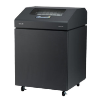
This chapter contains drawings of the electromechanical assemblies comprising the printer. Following each illustration is a list
of the illustrated parts and their part numbers. Items marked “Ref” (reference) are not spared, or are part of another assembly,
or are shown elsewhere.
Illustrated Parts Breakdown
Figure 35. Top Cover, Doors, Casters, and Shipping Kit for Cabinet Model............................................................ page 392
Figure 36. Paper Stacker and Chains ...................................................................................................................... page 394
NOTE: Parts for the power paper stacker are shown and listed in Appendix E.
Figure 37. Operator Panel and Cabinet Details ....................................................................................................... page 396
Figure 38. Pedestal Details, including Shipping Kit.................................................................................................. page 398
Figure 39. Inside Covers, Cabinet Model................................................................................................................. page 400
Figure 40. Inside Covers and Card Cage, Pedestal Model...................................................................................... page 402
Figure 41. Card Cage Fan Assembly, Pedestal Model ............................................................................................ page 404
Figure 42. Shuttle Assembly and Circuit Boards....................................................................................................... page 406
Figure 43. Magnetic Pickup Unit (MPU) and Extension Spring................................................................................ page 409
Figure 44. Tractor Shafts ......................................................................................................................................... page 411
Figure 45. Platen...................................................................................................................................................... page 413
Figure 46. Motors, Card Cage Fan, and Paper Detector Switch.............................................................................. page 416
Figure 47. Circuit Breaker ........................................................................................................................................ page 419
 Loading...
