261
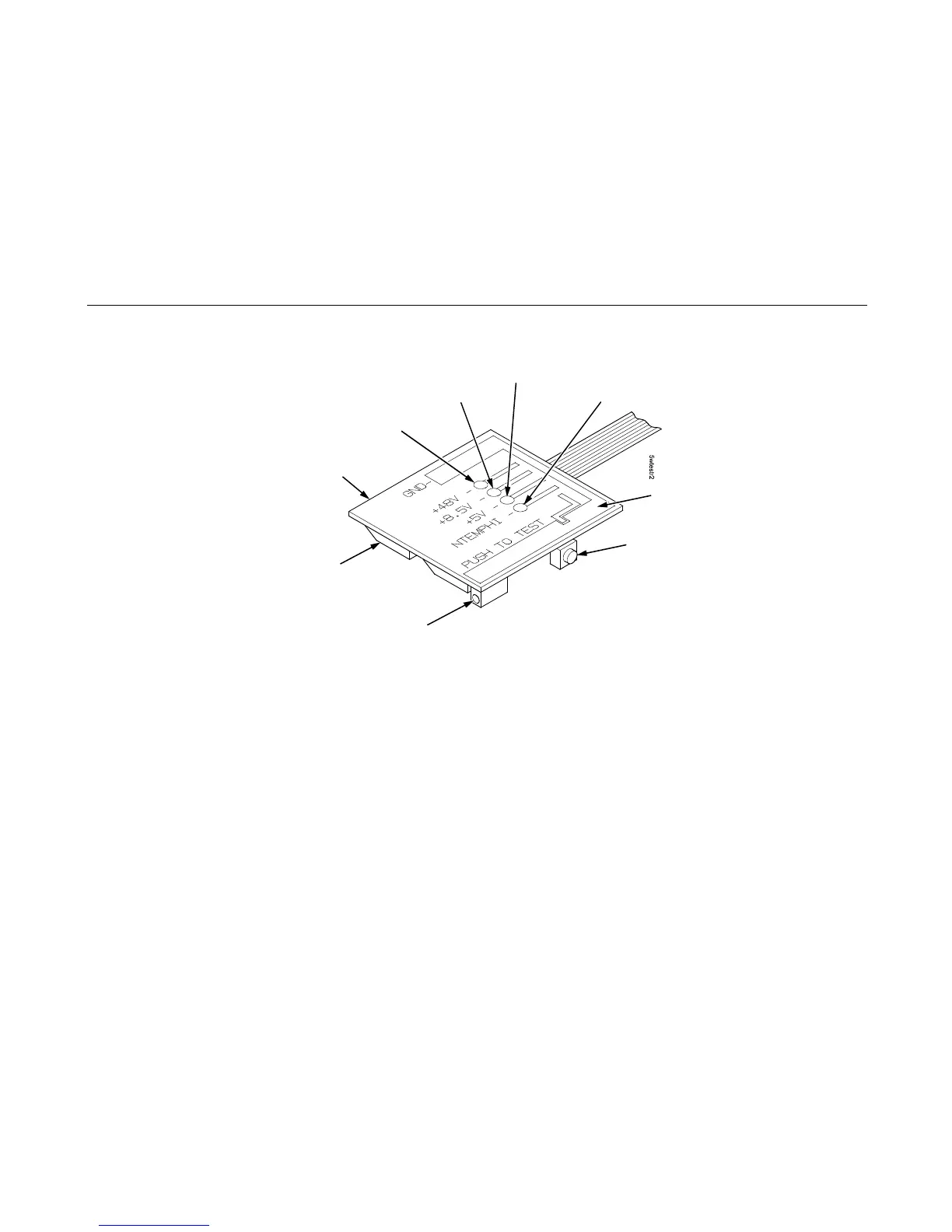
Figure 13. Testing the Power Supply
22. Set the printer’s power switch to O (off).
23. Unplug power supply connector P101 from the 12-pin connector on the power supply tester Load Block. (Figure 12.)
24. Connect power supply cable connector P101 to either the power stacker power cable or connector J101 on the controller
board. (Figure 12.)
25. Cabinet Model: Remove the paper guide assembly (page 348).
Pedestal Model: Remove the top cover assembly (page 327).
26. Return the printer to normal operation (page 314).
GND Test Jack: Insert Negative (-) Lead Here
+5 V Test Point
+8.5 V Test Point
NTEMPHI Test Point
Monitor Block
Push Button: Push to
activate +8.5 V and +48 V
and place an electrical
load on +5 V.
Rubber Foot
+48 V Test Point
Ground (GND) Pad
 Loading...


