Chapter 5 Removal And Replacement Procedures
324
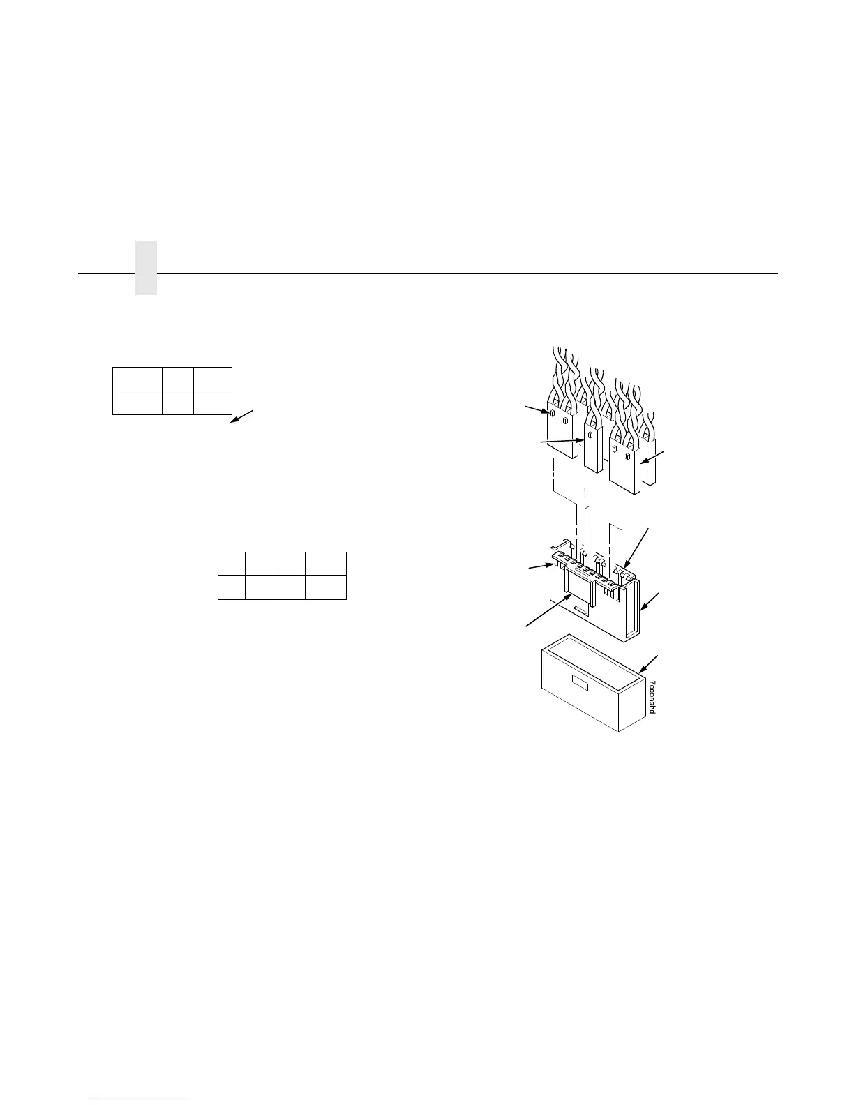
Figure 14. This figure shows how to assemble a cable connector shell.
CCF = Card Cage Fan
LRIB M = Left Ribbon Motor
LRP = Left Ribbon Guide
PLAT M = Platen Open Motor
PMD = Paper Motion Detector (Switch)
POD = Paper Out Detect (Switch)
CVO = Cover Open (Switch)
EHF* = Exhaust Fan
HBF = Hammer Bank Fan
MPU = Magnetic Pickup
PAPR M = Paper Feed Motor
PLO = Platen Open (Switch)
RRIB M = Right Ribbon Motor
RRP = Right Ribbon Guide
* JMP on pedestal models: used as a
spacer
8 6 4 2
7 5 3 1
12 1020 18 16 14
11 919 17 15 13
LRIB M
PLAT M
LRP
CCF
PMD
POD
P106 Connector Configuration
RRIB M
PAPR M
HBF
EHF
CVO
MPU
RRP
PLO
P107 Connector Configuration
Pin No.
8 6 4 2
7 5 3 1
12 1020 18 16 14
11 919 17 15 13
(Top View: As seen
when plugged into the
controller board.)
Typical 4-Wire
Cable Connector
Pull the sides outward just
enough to release the
connector lock tab from the
slot in the connector shell.
Connector shell
P106 / P107
P/N 14H5288
J106 or J107 on the
Controller Board
Key Tab
Typical 2-Wire
Cable Connector
Key Tab Slot
Push here to
remove the shell
from the controller
board.
(Top View: As seen
when plugged into the
controller board.)

 Loading...


