474
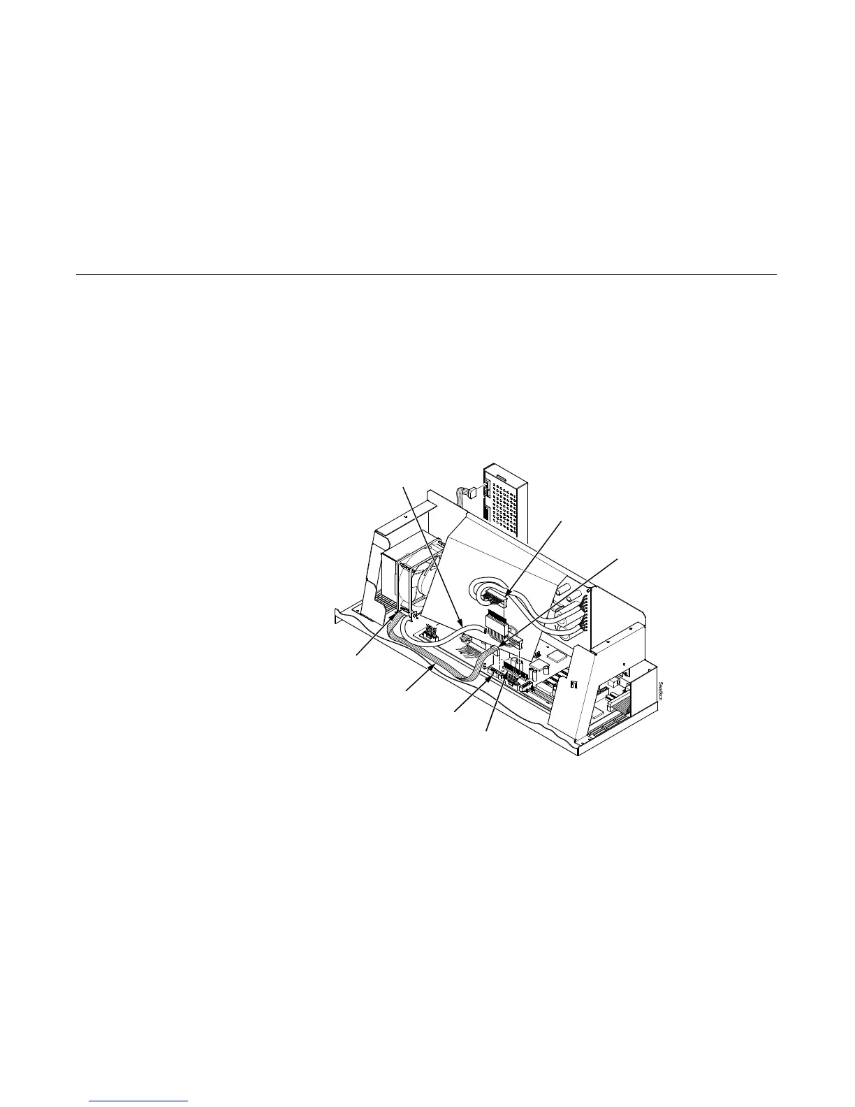
5. Connect the power stacker logic cable P103 to connector J117 on the controller board. (Figure 71.)
6. Disconnect the power supply cable from connector J101 on the controller board. (Figure 71.)
7. Connect power supply cable connector P101 to the stacker power cable, then connect the stacker power cable to
connector J101 on the controller board. (Figure 71.)
8. Route the stacker power cable in front of the controller board and down through the cutout under the card cage fan. (Figure
71.)
9. Route the stacker logic cable in front of the controller board and down through the cutout under the card cage fan. (Figure
71.)
Figure 71. This figure shows where to attach the power stacker power and logic cables on the PSA3 controller board.
Power Supply Connector P101
PSA3 Connector J101
Connector P103
Connector J117
Stacker Logic
Cable
Stacker Power Cable
Cutout Beneath
Card Cage Fan

 Loading...


