(there are very few). The
370
Processor Control Session
was also designed
to
be
keystroke efficient.
That
is, actions
you request require a minimum
amount
of
keystrokes.
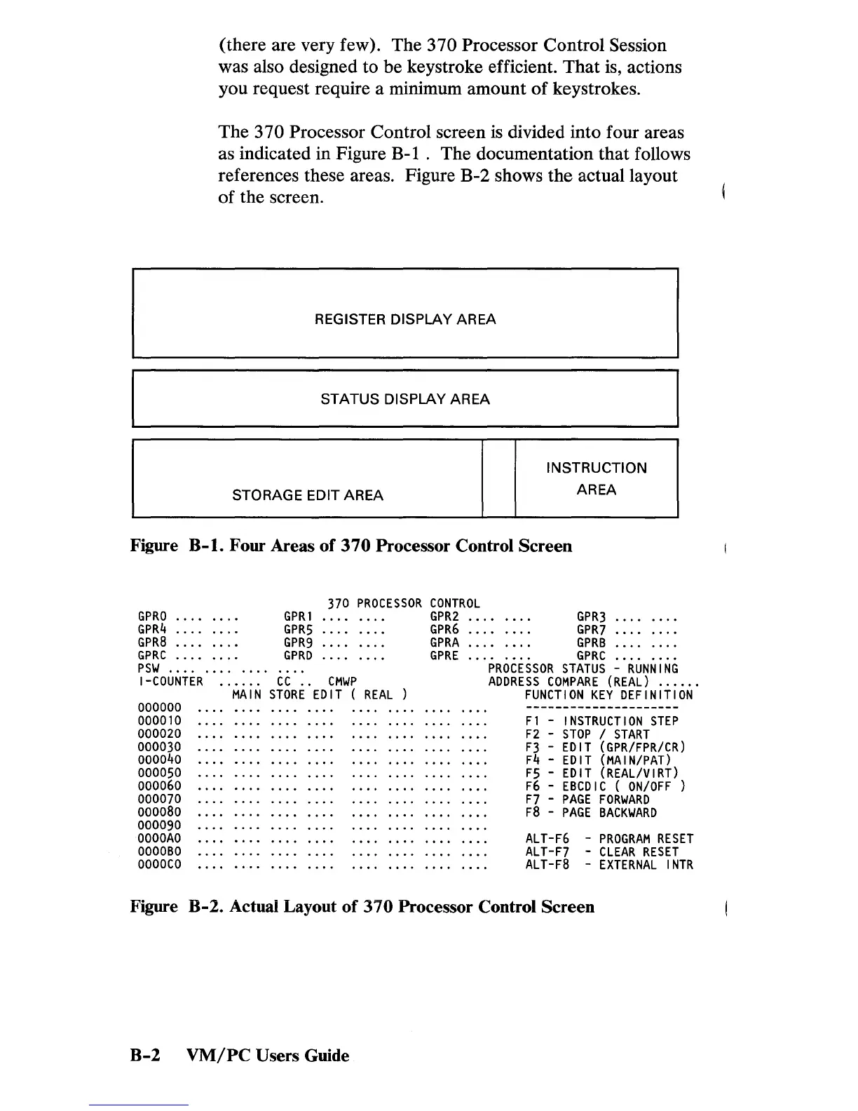
The
370
Processor Control screen is divided into four areas
as indicated in Figure B-1 .
The
documentation
that
follows
references these areas. Figure B-2 shows
the
actual layout
of
the screen.
REGISTER DISPLAY AREA
STATUS DISPLAY AREA
INSTRUCTION
STORAGE EDIT
AREA
AREA
Figure B-1. Four Areas
of
370
Processor Control
Screen
GPRO
GPR4
GPR8
GPRC
psw
...........
.
GPRI
GPR5
GPR9
GPRD
370
PROCESSOR
CONTROL
GPR2
GPR6
GPRA
GPRE
I-COUNTER
......
CC
..
CMWP
000000
000010
000020
000030
000040
000050
000060
000070
000080
000090
OOOOAO
OOOOBO
OOOOCO
MAIN
STORE
EDIT
(
REAL
GPR3
GPR7
GPRB
GPRC
PROCESSOR
STATUS
-
RUNNING
ADDRESS
COMPARE
(REAL)
.....
.
FUNCTION
KEY
DEFINITION
Fl
-
INSTRUCTION
STEP
F2
-
STOP
/
START
F3
-
EDIT
(GPR/FPR/CR)
F4
-
EDIT
(MAIN/PAT)
F5
-
EDIT
(REAL/VIRT)
F6
-
EBCDIC
(
ON/OFF)
F7
-
PAGE
FORWARD
F8
-
PAGE
BACKWARD
ALT-F6
-
PROGRAM
RESET
ALT-F7
-
CLEAR
RESET
ALT-F8
-
EXTERNAL
INTR
Figure B-2. Actual Layout
of
310
Processor Control Screen
B-2
VM/PC
Users Guide
 Loading...