Chapter 2. Introduction to IBM Flex System V7000 Storage Node 57
The disk drives connect to the Flex System Enterprise chassis through the midplane
interconnect for their power. Also, in the control enclosure, the midplane interconnect is used
for the internal control and I/O paths. The expansion enclosures use Serial Attached SCSI
(SAS) connections on the front of the control and expansion canisters for disk I/O and control
commands.
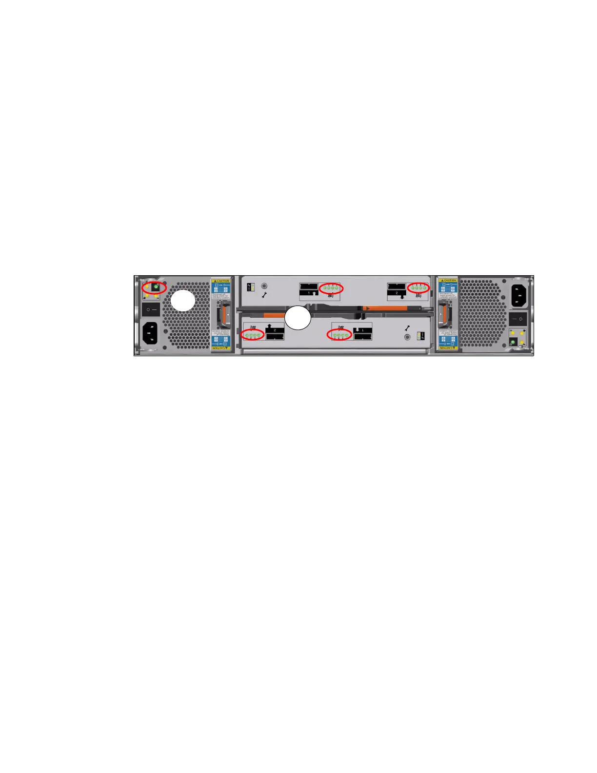
2.5.4 IBM Storwize V7000 expansion enclosure
The IBM Storwize V7000 expansion enclosure can be optionally attached to IBM Flex System
V7000 Storage Node externally for added capacity beyond that of the internal enclosures.
These expansion enclosures contain two IBM Storwize V7000
expansion canisters, disk
drives, and two power supplies. There are two models of the expansion enclosures with the
2076-212 providing 12 disk slots of the 3.5 inch form factor, and the 2076-224 providing 24
disk slots of the 2.5 inch drives form factor.
Figure 2-9 shows the components of the expansion enclosure.
Figure 2-9 Component side view Expansion enclosure
The expansion enclosure power supplies have a single power lead connector on the power
supply unit. The PSU has an IEC C14 socket and the mains connection cable has a C13 plug.
As shown in Figure 2-9, the PSU has one green status LED indicator (A) to show it is
powered on and working properly.
Each expansion canister provides two SAS interfaces that are used to connect to either IBM
Flex System V7000 Storage Node control or expansion enclosures or to a preceding IBM
Storwize V7000
expansion enclosure, as well as to connect any additional IBM Storwize
V7000
expansion enclosure behind it. The ports are numbered 1 on the left and 2 on the
right. SAS port 1 is the IN port and SAS port 2 is the OUT port. There is also a symbol printed
at the ports to identify whether it is an IN or an OUT bound port.
Use of the SAS connector 1 is mandatory when installed, as the expansion enclosure must
be attached to either a control enclosure or another expansion enclosure. SAS connector 2 is
optional, as it is used to attach to the next additional expansion enclosure in the chain.
Each port connects four SAS physical links (PHYs) to the drives. As shown in Figure 2-9,
there is an LED associated with each PHY in each port (eight LEDs in total per canister). The
LEDs are green and grouped together next to the ports (B); for each port they are numbered
1 through 4. These LEDs indicate when there is activity on the PHY.