WindO/I-NV4 User’s Manual 35-5
1 HG5G/4G/3G/2G-V
35
MICRO/I Specifications
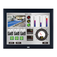
● Serial Interface (COM2)
Use applicable cables for wiring and recommended ferrules (made by Phoenix Contact) as follows.
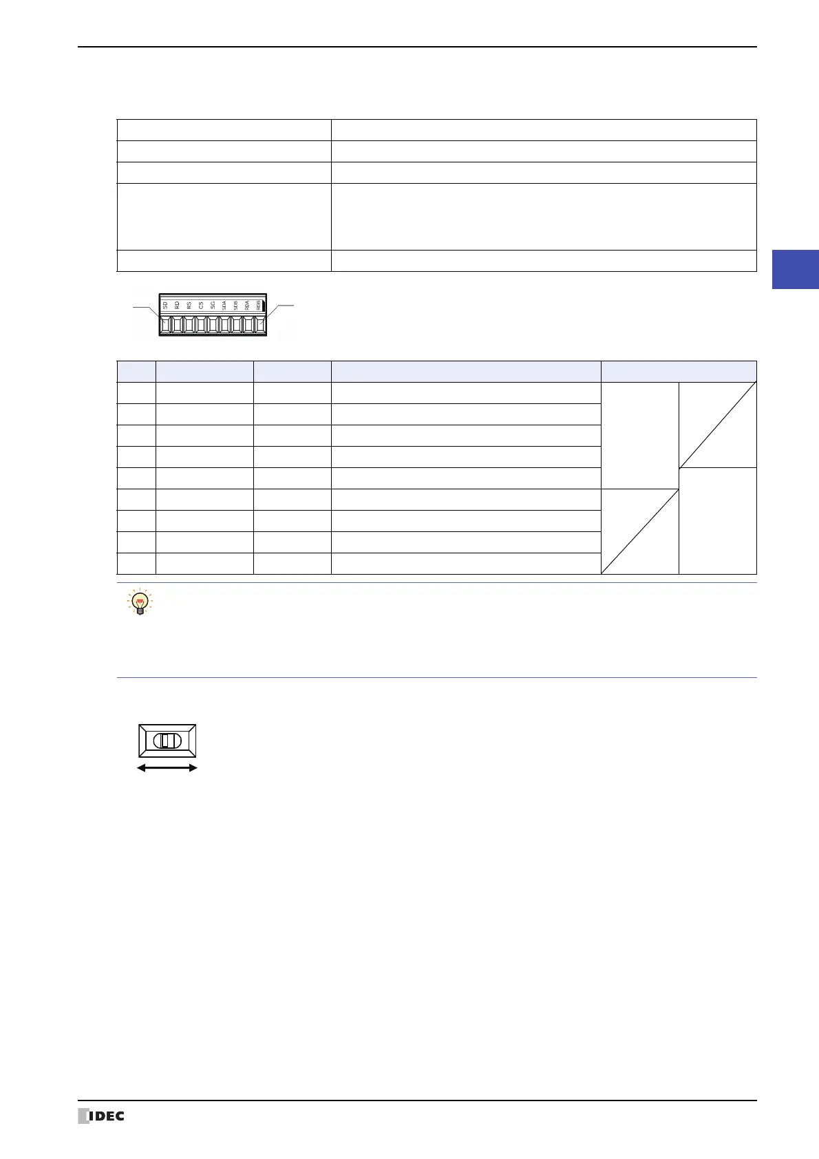
• Terminating Resistor Selector Switch (for RS422/485 interface)
When using RS422/485 interface, set the Terminating Resistor Selector Switch to the ON side. This will connect the
internal terminating resistor (120Ω) between RDA and RDB.
●
Expansion Module Interface (EXT)
IDEC MICROSmart expansion modules can be connected to the HG5G/4G/3G/2G-V.
Refer to Chapter 30 “1.2 Applicable Expansion Modules” on page 30-2 for the number, the types and the combination
of the expansion modules that can be installed.
Interface Specification RS232C, RS422/485
Connector Detachable Terminal Block 9-pin
Applicable cable AWG20 to AWG22
Recommended Pressure Terminal
AI 0,34-8 TQ
AI 0,5-8 WH
AI-TWIN 2 x 0,5-8 WH
(Phoenix Contact)
Tightening Torque 0.22 to 0.25 N•m
No. Name I/O Function Communication type
1SD OUT Send Data
RS232C
2 RD IN Receive Data
3RS OUT Request to Send
4CS IN Clear to Send
5SG ― Signal Ground
RS422/485
6 SDA OUT Send Data (+)
7 SDB OUT Send Data (-)
8 RDA IN Receive Data (+)
9 RDB IN Receive Data (-)
Only one crimp terminal can be inserted into a terminal hole.
Please set another terminal block in the vicinity of MICRO/I and connect SG when using "RS232C" and
"RS422/485" requiring crossover wiring at the same time.
Separate the communication cables so that they do not affect each communication waveform when using
RS232C and RS422/485 at the same time.
 Loading...