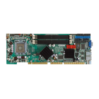
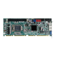
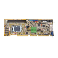
WSB-H810 PICMG 1.0 CPU Card
Page xiii
Table 3-28: SPI Flash Connector Pinouts ..................................................................................42
Table 3-29: SPI EC Flash Connector Pinouts ............................................................................43
Table 3-30: TPM Connector Pinouts...........................................................................................44
Table 3-31: USB 2.0 Connector Pinouts.....................................................................................45
Table 3-32: USB 2.0 Connector (Type A) Pinouts .....................................................................45
Table 3-33: USB 3.0 Connector Pinouts.....................................................................................46
Table 3-34: LAN Pinouts ..............................................................................................................47
Table 3-35: Connector LEDs........................................................................................................48
Table 3-36: USB 2.0 Port Pinouts................................................................................................48
Table 3-37: VGA Connector Pinouts...........................................................................................49
Table 4-1: AT/ATX Power Mode Switch Settings.......................................................................65
Table 4-2: Flash Descriptor Security Override Jumper Settings.............................................65
Table 4-3: BIOS Options and Configured USB Ports................................................................66
Table 4-4: USB Power Source Setup..........................................................................................67
Table 5-1: BIOS Navigation Keys................................................................................................72
Table 5-2: BIOS Options and Configured USB Ports............................................................. 100
 Loading...
