WSB-H810 PICMG 1.0 CPU Card
Page 29
Function Pin Description Function Pin Description
Power LED 1 +5V Speaker 2
BEEP_PWR
3 N/C 4 N/C
5 GND 6 N/C
Power Button 7 PWRBTN_SW# 8
PC_BEEP
9 GND Reset 10 N/C
HDD LED 11 +5V 12 EXTRST-
13 SATA_LED# 14 GND
Table 3-12: Front Panel Connector Pinouts
3.2.12 I
2
C Connector
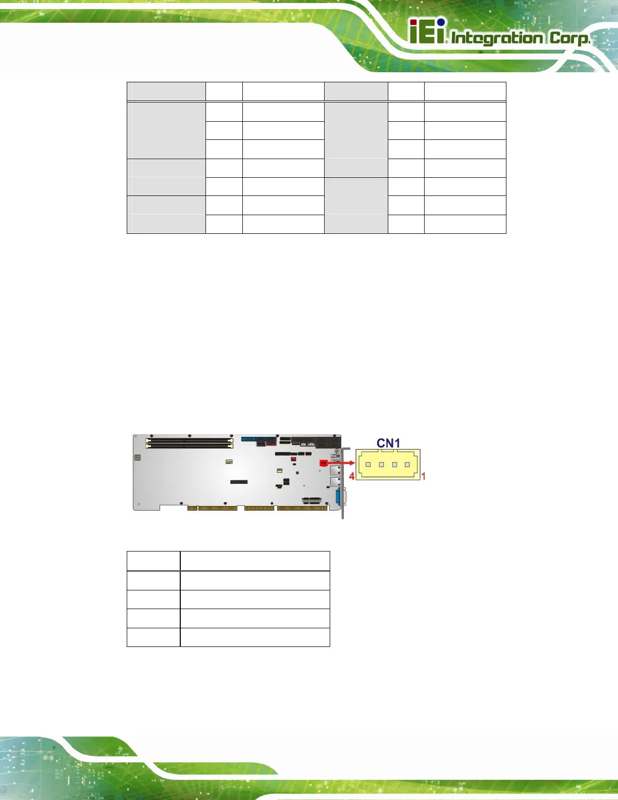
CN Label: CN1
CN Type:
4-pin wafer, p=1.25 mm
CN Location:
See
Figure 3-13
CN Pinouts:
See
Table 3-13
The I
2
C connector is for system debug.
Figure 3-13: I
2
C Connector Location
Pin Description
1 GND
2 I2C_DAT
3 I2C_CLK
4 +5V
Table 3-13: I
2
C Connector Pinouts

 Loading...


