WSB-H810 PICMG 1.0 CPU Card
Page 24
Pin Description
1 Battery+
2 GND
Table 3-6: Battery Connector Pinouts
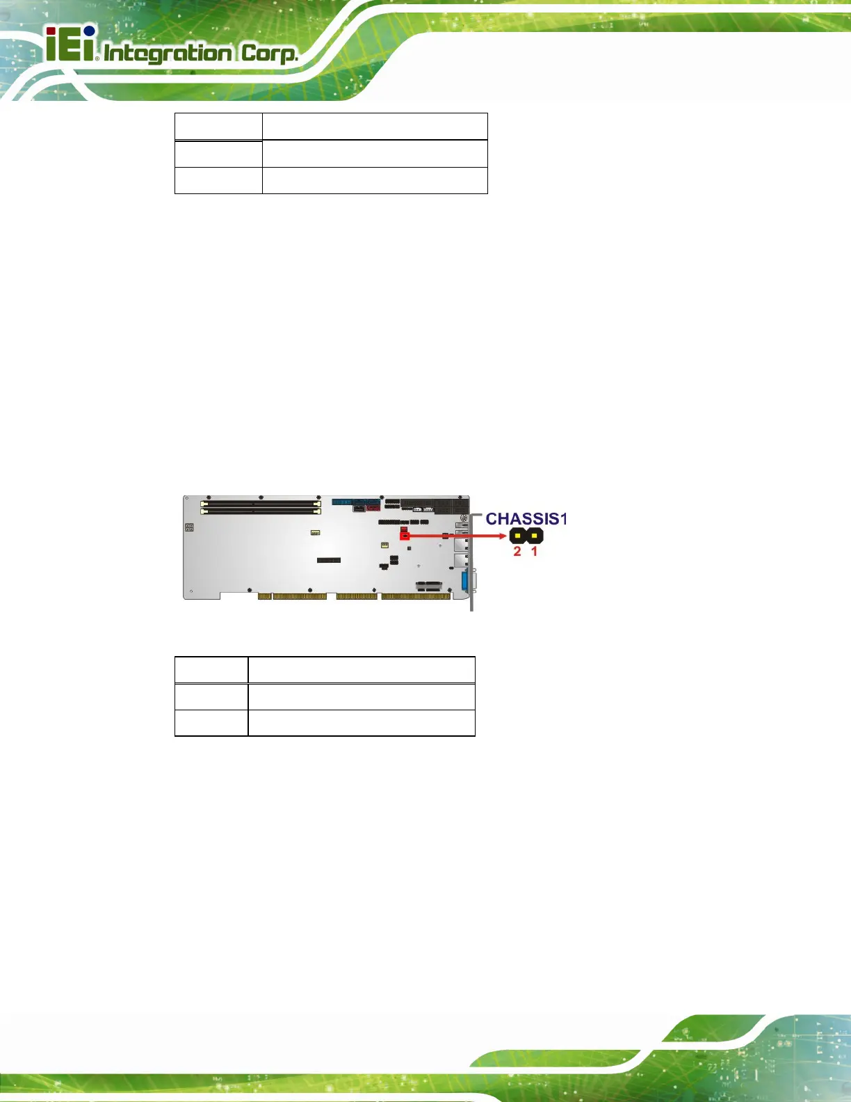
3.2.5 Chassis Intrusion Connector
CN Label: CHASSIS1
CN Type:
2-pin header, p=2.54 mm
CN Location:
See
6Figure 3-6
CN Pinouts:
See
Table 3-7
The chassis intrusion connector is for a chassis intrusion detection sensor or switch that
detects if a chassis component is removed or replaced.
Figure 3-6: Chassis Intrusion Connector Location
Pin Description
1 +3.3VSB
2 CHASSIS OPEN
Table 3-7: Chassis Intrusion Connector Pinouts
3.2.6 DDR3 DIMM Slots
CN Label: CHA_DIMM1, CHB_DIMM1
CN Type:
DDR3 DIMM slot
CN Location:
See 6Figure 3-7
The DIMM slots are for DDR3/DDR3L DIMM memory modules.

 Loading...


