WSB-H810 PICMG 1.0 CPU Card
Page 54
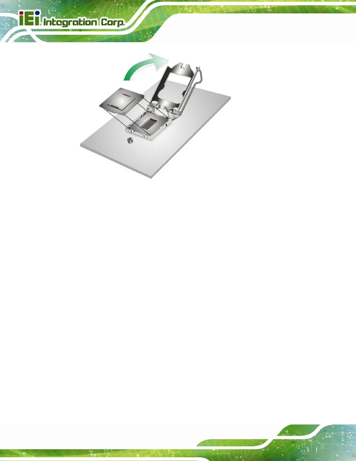
Figure 4-2: Remove Protective Cover
Step 3: Inspect the CPU socket. Make sure there are no bent pins and make sure the
socket contacts are free of foreign material. If any debris is found, remove it with
compressed air.
Step 4: Orientate the CPU properly. The contact array should be facing the CPU
socket.
Step 5: Correctly position the CPU. Match the Pin 1 mark with the cut edge on the
CPU socket.
Step 6: Align the CPU pins. Locate pin 1 and the two orientation notches on the CPU.
Carefully match the two orientation notches on the CPU with the socket
alignment keys.
Step 7: Insert the CPU. Gently insert the CPU into the socket. If the CPU pins are
properly aligned, the CPU should slide into the CPU socket smoothly. See
Figure 4-3.

 Loading...


