WSB-H810 PICMG 1.0 CPU Card
Page 21
3.2 Internal Peripheral Connectors
The section describes all of the connectors on the WSB-H810.
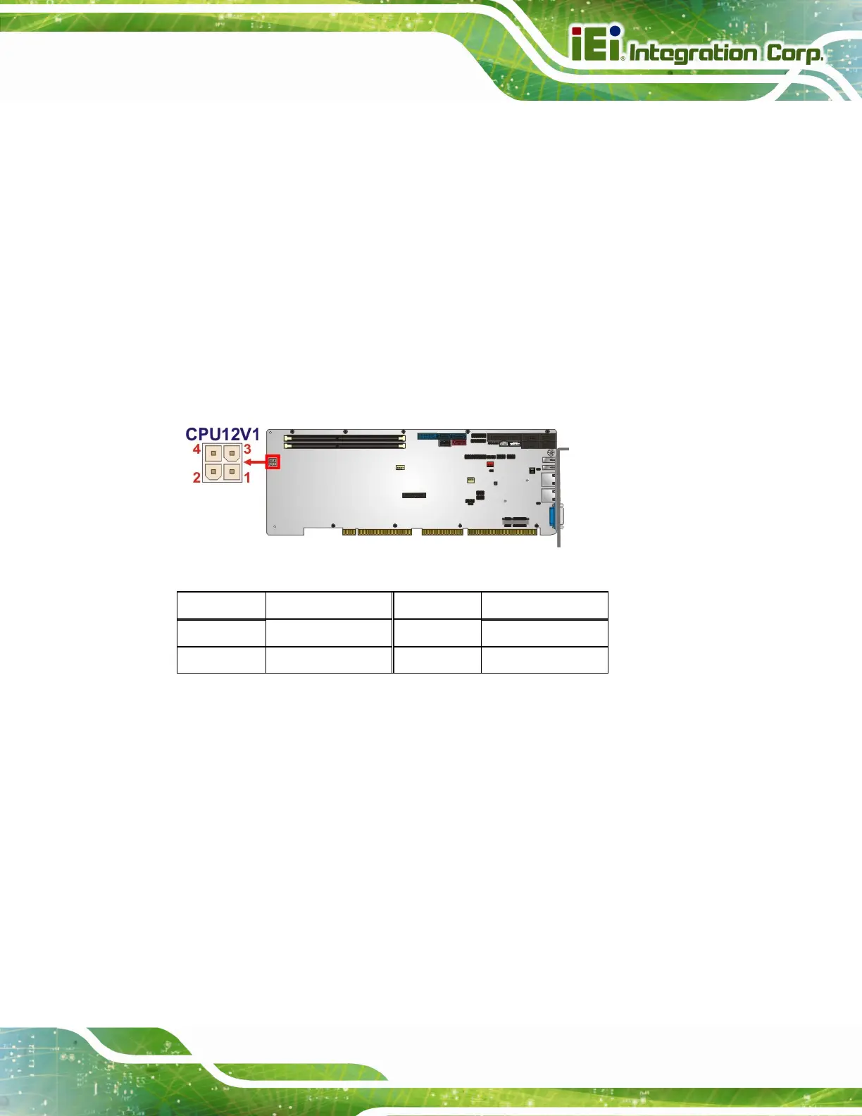
3.2.1 +12V Power Connector
CN Label: CPU12V1
CN Type:
4-pin Molex power connector, p=4.2 mm
CN Location:
See
Figure 3-2
CN Pinouts:
See
Table 3-3
This connector provides power to the CPU.
Figure 3-2: +12V Power Connector Pinout Location
Pin Description Pin Description
1 GND 2 GND
3 +12V 4 +12V
Table 3-3: +12V Power Connector Pinouts
3.2.2 ATX Power Supply Enable Connector
CN Label: ATXCTL1
CN Type:
3-pin wafer, p=2.54 mm
CN Location:
See
Figure 3-3
CN Pinouts:
See
Table 3-4
The ATX power supply enable connector enables the WSB-H810 to be connected to an
ATX power supply. To enable an ATX power supply, the AT and ATX power mode
selection switch must also be configured. Please refer to Chapter 4 for more details.

 Loading...


