WSB-H810 PICMG 1.0 CPU Card
Page 28
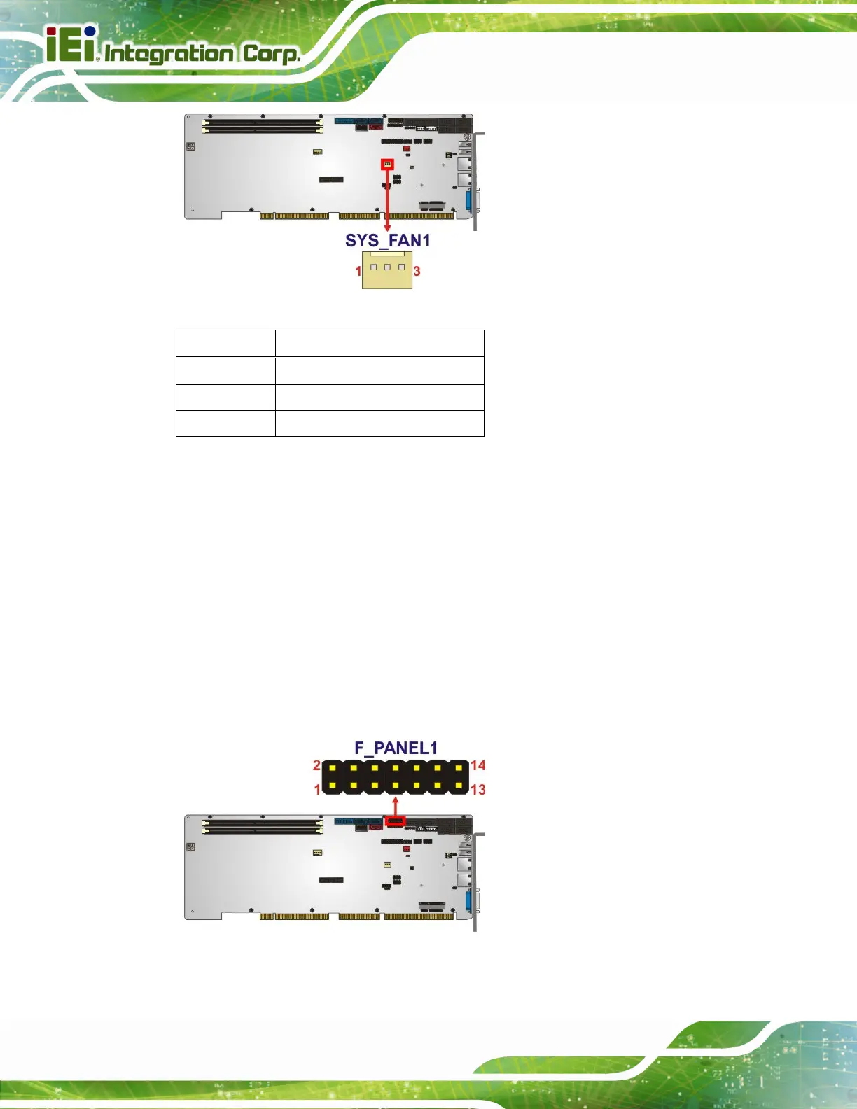
Figure 3-11: System Fan Connector Location
Pin Description
1 FANIO
2 +12 V (PWM)
3 GND
Table 3-11: System Fan Connector Pinouts
3.2.11 Front Panel Connector
CN Label: F_PANEL1
CN Type:
14-pin header, p=2.54 mm
CN Location:
See Figure 3-12
CN Pinouts:
See Table 3-12
The front panel connector connects to the indicator LEDs and buttons on the computer's
front panel.
Figure 3-12: Front Panel Connector Location

 Loading...


