- 81 -
IS810N-INT Series Servo System User Manual (Brief)Chapter 4 Wiring
Chapter 4 Wiring
DANGER
Wiring must be performed by authorized and qualied personnel.
Before removing or installing the drive, turn off the power, wait ve minutes until the power
indicator becomes off, and verify that the voltage between and Θ is zero using a multimeter.
Perform wiring after the servo drive and motor are installed properly. Failure to comply will
result in electric shocks.
Do not damage the cables, lay them under large tension or pressure, or hang them. Failure to
comply may result in electric shock.
Insulate the power terminal connectors to prevent electric shocks.
The specications and installation methods of external cables must comply with the applicable
local regulations.
The cables described in Table 4-5 must be made of copper and the grounding cables must be
yellow-green cables.
The entire system must be grounded.
CAUTION
Carry out wiring correctly. Failure to comply will result in abnormal actions of the servo motor
and personal injuries.
Prevent incorrect terminal connection. Failure to comply may result in damages to the
terminals.
Connect the electromagnetic contactor between the power supply and main circuit of the
drive (L1, L2 for single-phase, R, S, T for three-phase). If no electromagnetic contactor is
connected, a re may occur when a fault occurs and continuous large current ows through
the product.
Use the ALM (fault signal) to cut off the main circuit power supply. When the braking transistor
becomes faulty, the regenerative resistor may become overheated, causing a re.
Before power-on, check the voltage specications of the drive. Check whether the input power
supply is correct (380 VAC to 480 VAC, 50/60 Hz).
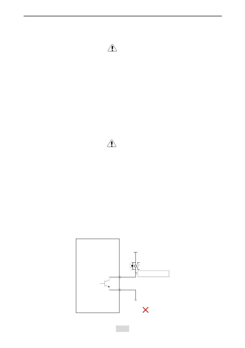
Do not reverse the ywheel diode. Failure to comply will damage the product and affect signal
output.
Servo drive
External 5-24 VDC
DO1-
DO1+
Relay
Incorrect polarity of
flywheel diode
External 0 V
Use a noise lter to reduce electromagnetic interference on electronic devices around the
product.
 Loading...