- 112 -
IS810N-INT Series Servo System User Manual (Brief) Chapter 4 Wiring
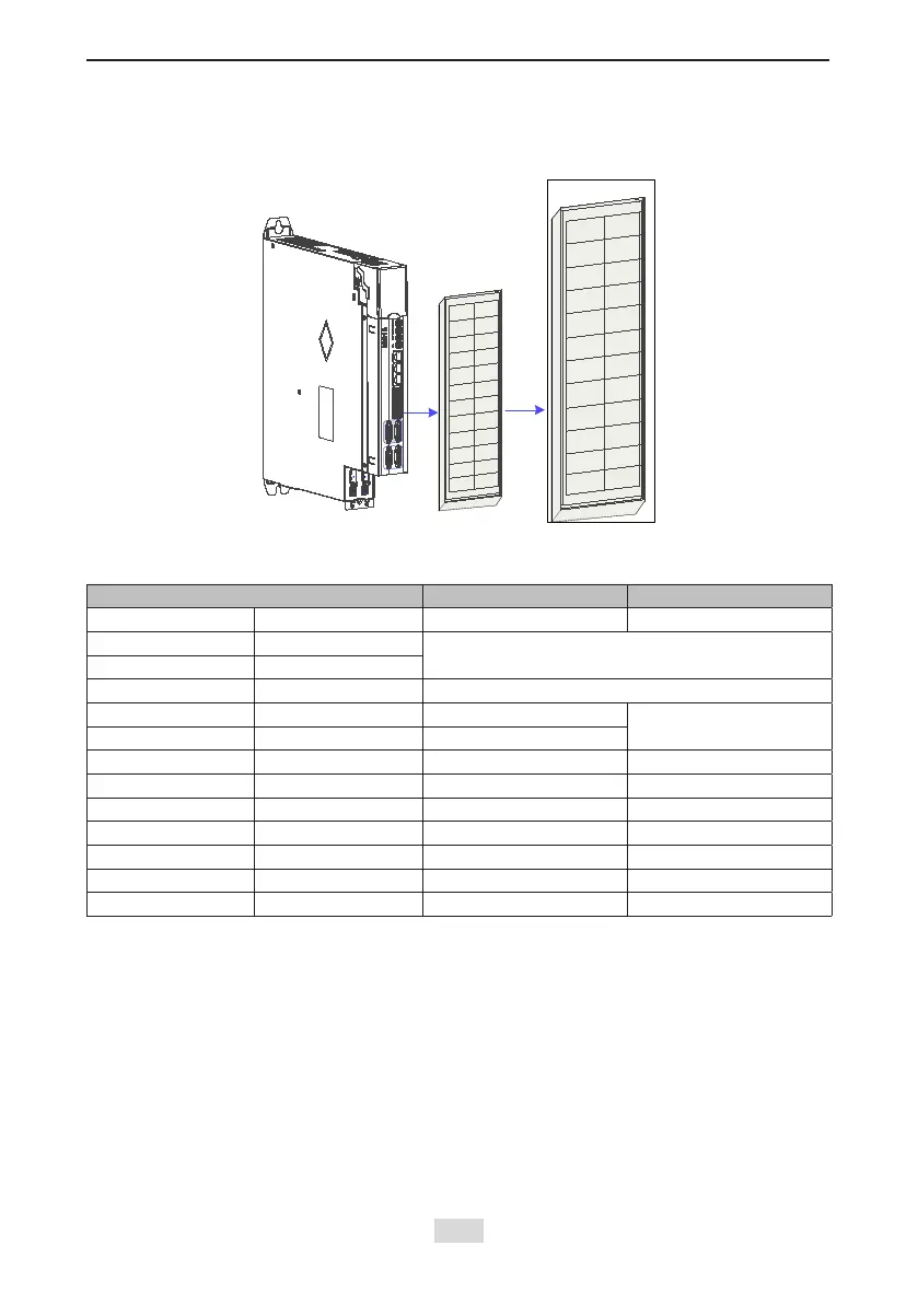
4.8 Control Signal Connection (CN1)
Figure 4-25 Pin layout of the control circuit terminal connector of a servo drive
Axis1
Axis2
+24V
COM-
COM+
DO1+
DO1-
DI1
DI2
DI3
HDI4+
HDI4-
HDI4
PE
+24V
COM-
COM+
DO2+
DO2-
DI5
DI6
DI7
HDI8+
HDI8-
HDI8
PE
CN1
1
2
3
4
5
6
7
8
9
10
11
12
13
14
15
16
17
18
19
20
21
22
23
24
CN1
1
.
CN1 Terminal
Table 4-17 DI/DO signal description
Terminal Symbol Terminal Name Terminal Function
Axis 1 Axis 2 - -
+24 V +24V
Internal 24 V power supply, voltage range:
20 to 28 V, maximum output current: 200 mA
COM- COM-
COM+ COM+ Power input (12 V to 24 V)
DO1+ DO2+ S-RDY+
Servo ready
DO1- DO2- S-RDY-
DI1 DI5 P-OT Positive limit switch
DI2 DI6 N-OT Negative limit switch
DI3 DI7 INHIBIT Pulse input inhibited
HDI4+ HDI8+ TouchProbe Touch probe function
HDI4- HDI8- TouchProbe Touch probe function
HDI4 HDI8 TouchProbe Touch probe function
PE PE Shield Signal shielding ground
 Loading...