- 83 -
IS810N-INT Series Servo System User Manual (Brief)Chapter 4 Wiring
4.2.2 Function Description of Terminals in Drive Unit
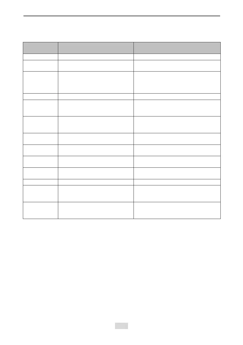
Table 4-1 Terminal names and functions
Terminal
Symbol
Terminal Name Terminal Function
+, - Power input terminals Bus input
U, V, W Servo motor connection terminals
Connected to the U, V and W phases of
the servo motor.
PE Ground
Two grounding terminals of the servo
drive are respectively connected to
those of the power supply and the servo
motor.
CN1 Control signal terminal Digital signal input/output
CN2 EtherNET communication terminal
Connected for transmitting background
communication signals and online
upgrade signals
CN3/CN4 EtherCAT communication terminal
EtherCAT network ports for connecting
CN3(OUT) to the next slave and CN4(IN)
to the host controller or previous slave
CN5/CN7 Encoder 1 terminal (DB15)
Encoder signal frequency division output
and full closed-loop signal input (port 1)
CN6/CN8 Encoder 2 terminal (DB9)
Connected for transmitting servo motor
encoder signals (port 2)
BRAKE-OUT
BRAKE-COM
Brake terminal
Connected to the servo motor brake
terminal
RJ45A/RJ45B RJ45 communication port
RJ45B: Connected to the external LCD
keypad
STO AX1/AX2 STO connection terminal Safety function terminal
24 V/COM 24 V power port
External 24 V control power and brake
power input ports. For usage details,
refer to section 4.3.3.
24 V/COM 24 V power port
External 24 V control power and brake
power input ports. For usage details,
refer to section 4.3.3.

 Loading...