IS810N-INT Series Servo System User Manual (Brief) Chapter 6 Commissioning Software
- 156 -
6.1.1 Check Before Run
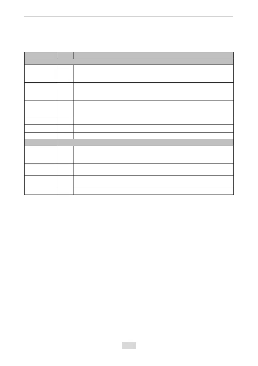
Check the items in the following table before running the servo drive and motor.
Table 6-1 Pre-running checklist
Applicable No. Activity
Wiring
□ 1
The main circuit power input terminals R, S, and T of the power supply
unit are connected correctly. The input power specications are 380
VAC to 480 VAC, 50/60 Hz.
□
2
The motor shaft main circuit output terminals U, V, and W of the drive
unit are properly connected to the power cables U, V, and W of the
servo motor in the correct phase sequence.
□
3
The signal wires of the servo drive are connected correctly. The
external signal wires such as the brake and the limit switch wires are
connected reliably.
□
4
The servo drive and motor are grounded reliably.
□
5
The cable tension is within the permissible range.
□
6
The wiring terminals have been insulated.
Environment and Mechanical Conditions
□
1
No foreign object, such as wire heads or metal powder which may
cause short circuit of the signal wires and power cables, exists inside
or outside the servo drive.
□
2
The servo drive or external regenerative resistor is not placed on
ammable objects.
□
3
Servo motor installation as well as shaft and mechanical connection
are reliable.
□
4
The servo motor and connected machine are ready to run.
6.1.2 Power Supply Connection
Connect the power supply of the main circuit.
After connecting the power supply of the main circuit, if the bus voltage indicator is in normal
display and the keypad displays “Reset”, “Nrd”, and “Rdy” in sequence, it indicates that the
servo drive is ready to run and waiting for the S-ON signal from the host controller.
6.1.3 Jogging
Perform jogging to check whether the motor can rotate properly without abnormal vibration
or noise. This operation can be performed via the keypad in speed mode, Inovance servo
commissioning software in speed mode and keypad in position mode.
Note:
The acceleration and deceleration time constants of speed/position reference can be set
through H06-12 (2006-0Dh) during jogging.
1) Jogging via the keypad in speed mode
Switch to H0D-11 on the keypad to enter the speed jogging mode, and the keypad displays
the default jogging speed. Press the UP/DOWN key to set the jogging speed, and press the
ENTER key to enter the jogging state. The keypad displays "JOG". Then, press the UP/DOWN
key to perform forward or reverse jogging. Press the MODE key to exit the jogging mode.

 Loading...