- 132 -
IS810N-INT Series Servo System User Manual (Brief) Chapter 5 Keypad
Chapter 5 Keypad
5.1 Introduction to LED Keypad
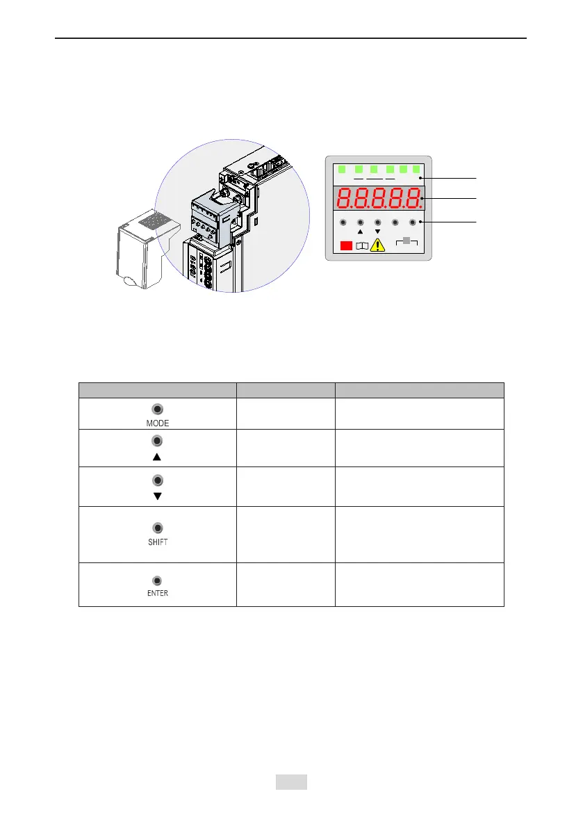
Figure 5-1 LED keypad appearance
RUN
SHIFT
MODE
ENTER
FWD
REV
ERR/TC
TUNE
A V
CHARGE
i
Function
indicator
LED display
area
Operating
keys
Ax1 Ax2
RUN
RPM
Hz
The keypad consists of the 5-digit 7-segment LEDs and keys. The keypad is used for display,
parameter setting, user password setting and general functions operations.
1. Function Description of Keys
Table 5-1 Functions of keys on the keypad
Key Key Name Function Description
MODE
Switch between modes.
Return to the upper-level menu.
UP
Increase the number indicated
by the blinking digit.
DOWN
Decrease the number indicated
by the blinking digit.
SHIFT
Shift the blinking digit.
View the high digits of the
number consisting of more than
5 digits.
ENTER
Switch to the next-level menu.
Execute commands such as
saving parameter values.

 Loading...