- 105 -
IS810N-INT Series Servo System User Manual (Brief)Chapter 4 Wiring
4.4.5 Connection to an MS1H Series Servo Motor
1. Power Cable Connection
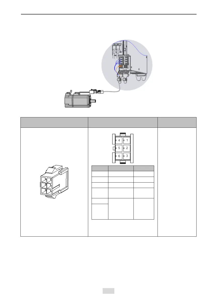
Table 4-17 Connectors of power cables on the servo motor side
Connector Appearance Terminal Pin Layout
Frame Size of
Applicable Motor
Black 6-pin connector
Pin No. Signal Remarks
1 U White
2 V Black
4 W Red
5 PE
Yellow/
Green
3 Brake
(without
positive and
negative)
6
Recommendation:
Plastic housing: MOLEX-50361736
Terminal: MOLEX-39000061
40 (Z series)
60 (Z series)
80 (Z series)
Note: Frame size of the motor indicates the width of the installation ange.
The power cable colors are subject to the actual cables. The cable colors mentioned in this
user guide are colors of Inovance cables.
2. Absolute Encoder Cable Connection
Refer to section 4.4.3 "2 Encoder Cable Connection".
 Loading...