- 104 -
IS810N-INT Series Servo System User Manual (Brief) Chapter 4 Wiring
Table 4-16 Recommended cable sizes
Cable Size Ω/km Allowed Cable Length (m)
26AWG (0.13 mm
2
) 143 10.0
25AWG (0.15 mm
2
) 89.4 16.0
24AWG (0.21 mm
2
) 79.6 18.0
23AWG (0.26 mm
2
) 68.5 20.9
22AWG (0.32 mm
2
) 54.3 26.4
21AWG (0.41 mm
2
) 42.7 33.5
To determine the length of the signal cable, consider voltage drop caused by the cable
resistance, and pay attention to the power capacity during power distribution, to ensure that the
strength of signals and power arriving at the drive input side is sufcient. Twisted-pair shield
cables sized greater than 26AWG are recommended.
The encoder cable and signal cable must be separated by at least 30 cm.
If the encoder cable is too short and an extension cable is to be added, make sure the shielded
layers of two separate cables are well connected for reliable grounding.
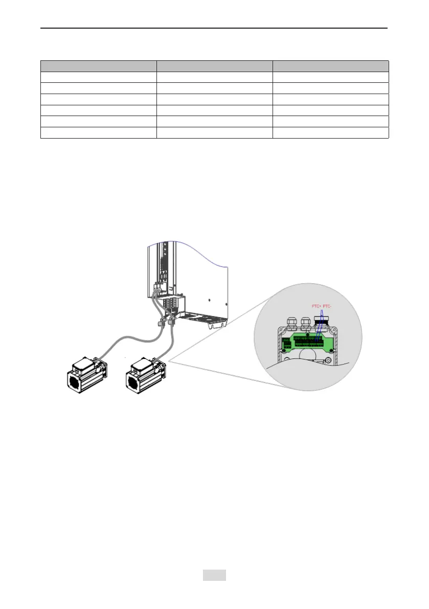
Wiring for Motor Temperature Detection:
Figure 4-14 Example of connecting the PTC+/PTC- signal cables
PTC+ and PTC- signals are
connected using the encoder cable
 Loading...