- 121 -
IS810N-INT Series Servo System User Manual (Brief)Chapter 4 Wiring
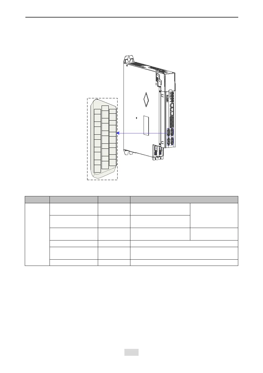
4.9 Encoder Signal Frequency Division Output and Full Closed-loop
Signal Input Connection (CN5/CN7)
Figure 4-26 CN5/CN7 terminal
PZO-
+5V
GND
PAO+
PBO+
GND
GND
GND
PAO-
PBO-
1
6
5
PZO+
10
11
15
CN5/CN7
-
-
-
-
1. Terminal CN5/CN7/DB15 Denition
Signal Default Function Pin No. Function
General
PAO+
PAO-
1
2
Phase A frequency-
division output signal
Phases A+B
quadrature
frequency-division
pulse output signal
PBO+
PBO-
3
4
Phase B frequency-
division output signal
PZO+
PZO-
8
6
Phase Z frequency-
division output signal
Home pulse output
signal
GND 9, 11, 13, 15 Home pulse OC output signal ground
+5 V 7
5 V internal power supply,
maximum output current: 200 mA
Reserved 5, 10, 12, 14 Reserved
The encoder frequency-division output circuit outputs differential signals via the differential
drive. Generally, it provides feedback signals to the host controller in the closed-loop position
control system. A differential or optocoupler circuit shall be used in the host controller to
receive feedback signals. The maximum output current is 20 mA.

 Loading...