- 101 -
IS810N-INT Series Servo System User Manual (Brief)Chapter 4 Wiring
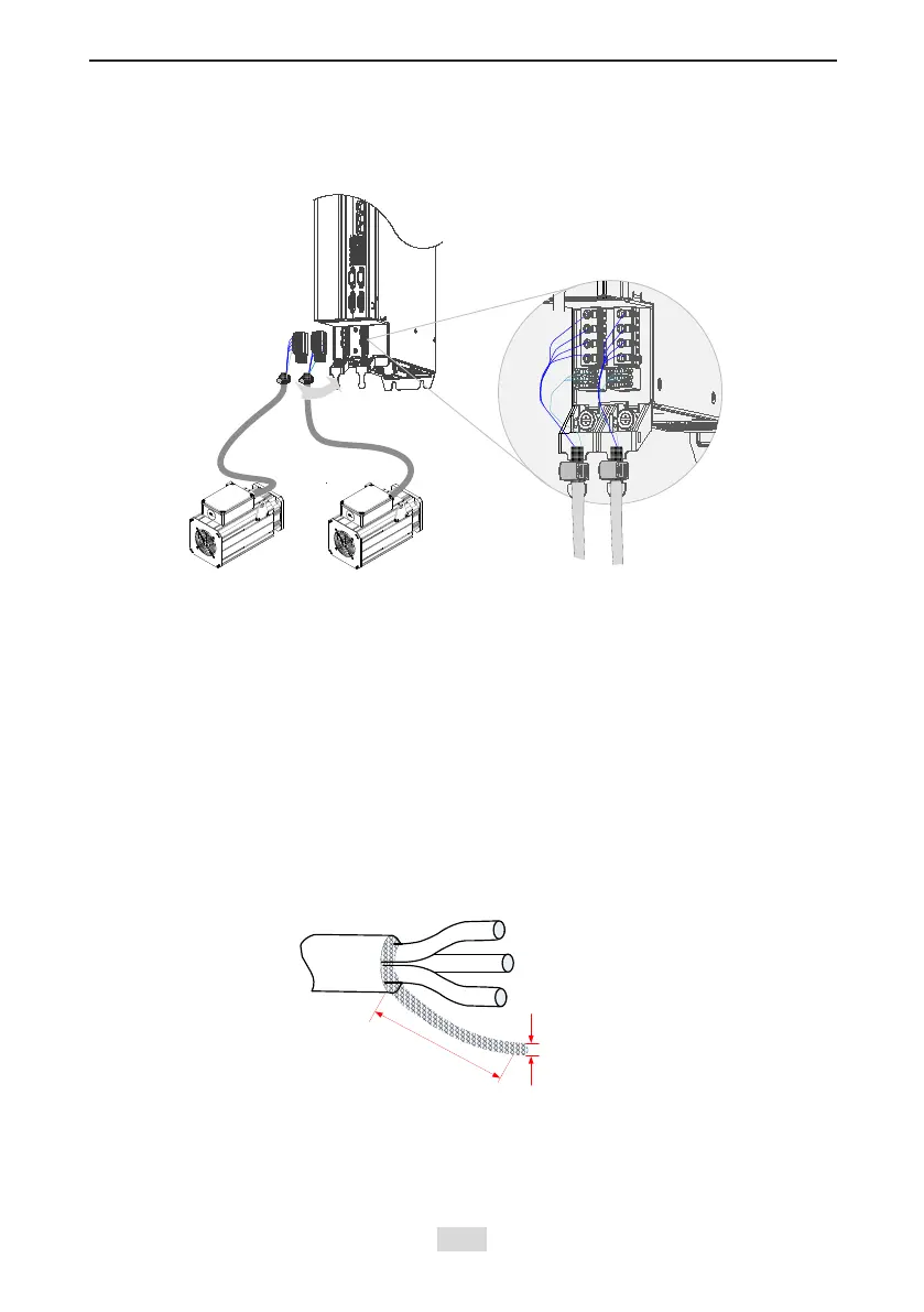
4.4.4 Connection to an ISMG Series Servo Motor
1. Power Cable Connection
Figure 4-11 Example of drive unit output connection to an ISMG series servo motor
Effect diagram after fixing is
completed
The specications and connections of external main circuit cables must comply with local
regulations and related IEC requirements.
To avoid equipment damages or operating faults, do not connect a capacitor or surge absorber
to the output side of the servo drive.
Long motor cables can contribute to electrical resonance caused by distributed capacitance
and inductance. In some cases, this might cause equipment damages in the drive, motor, or
cables. To avoid these problems, install an AC output reactor close to the drive if the cable is
longer than 100 m.
It is recommended to use shielded cable as the output cables to the motor. Connect the shield
with a grounding support fully to the ground, and connect the lead-out wire of the shield to the
PE terminal.
Ensure that the lead-out wire of the motor cable shield is as short as possible, and the width b
is greater than or equal to 1/5 of the length.
Figure 4-9 Lead-out wire of a motor cable shield
PE
For personal safety and reliability of the equipment, it is important to connect PE to an effective
electrical grounding cable. Resistance value of the grounding cable must be less than 10 Ω.
Do not connect the PE of the drive to the neutral conductor of the power system.
Use a proper grounding cable with yellow/green insulation for protective grounding conductor.
 Loading...