- 102 -
IS810N-INT Series Servo System User Manual (Brief) Chapter 4 Wiring
Ground the shield correctly.
It is recommended that the drive be installed on a metal mounting surface and ensure proper
contact between the conductive base of the drive and the metal mounting surface.
Install lter and drive on the same mounting surface to ensure the ltering effect.
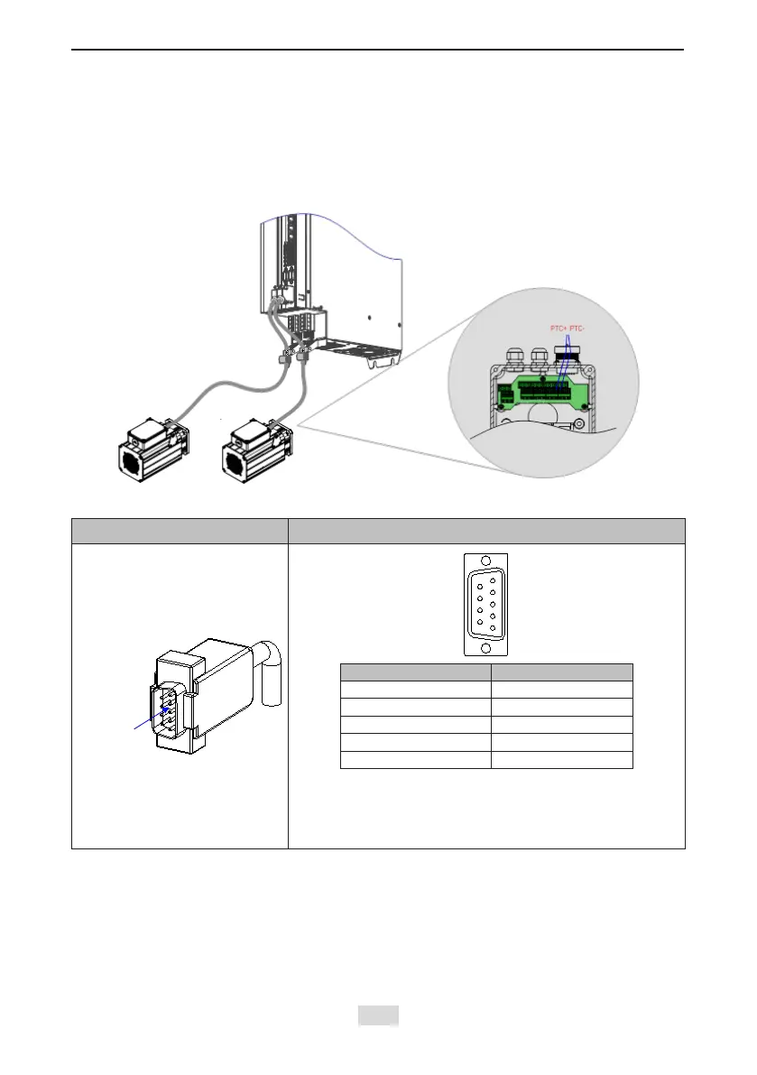
2. Encoder Cable Connection
Figure 4-13 Example of connecting encoder signal cables
Table 4-13 Connectors of encoder cables on the servo drive side
Connector Appearance Terminal Pin Layout
Pin No. Signal
1 PS+
2 PS-
7 +5 V
8 GND
Housing PE
Recommendation:
Plastic housing of plug on cable side: DB9P (SZTDK), black
housing
Core: DB9P soldering plug (SZTDK), blue rubber
PTC+ and PTC- signals are
connected using the encoder cable
 Loading...