IS810N-INT Series Servo System User Manual (Brief)Chapter 3 Installation
- 71 -
Shaft end Flat key
RH
0
-0.20
WK
0
-0.036
W
0
-0.022
7
0
-0.09
45
KA1
KB1
LL
4
LR
φ
110
0
-0.035
φ
S
0
-0.013
14
50.50
43.70
0.06
A
0.02 A
0.10 A
EQS
EQS
TP
φ
145
130
45
°
4×R
21
9×
φ
9
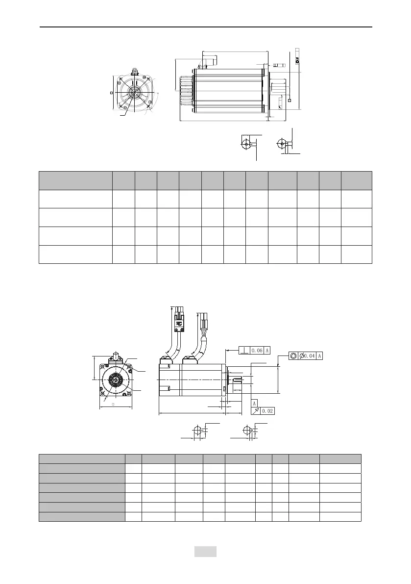
Model
LL
(mm)
LR
(mm)
LW
(mm)
S
(mm)
RH
(mm)
WK
(mm)
W
(mm)
TP
(mm)
KA1
(mm)
KB1
(mm)
Weight
(kg)
ISMH3-18C15CD-
A351B-Om19
214 55 / 19 / / / M6×18 94 143.5 10.5
ISMH3-18C15CD-
A351B-Om24
214 55 / 24 / / / M8×20 94 143.5 10.5
ISMH3-56C30CD-
A351B-Om24
274 55 / 24 / / / M8×20 94 203.5 14.5
ISMH3-56C30CD-
A331B-Om24
274 55 45 24 20 8 8 M8×20 94 203.5 14.5
3.3.4 Overall Dimensions of the ISMH Servo Motor Series
1) Overall Dimensions of the ISMH1 Servo Motor Series (100 W, 200 W, 400 W, 550 W, 750 W,
1.0 kW)
LL
LG
LE
LR
KW N9 W h8
T h8
LJ
φS
h6
φLB
h7
LK
KH
LC
LZ
φLA
TP
LH
500
500
Shaft end dimensions Keyed shaft end dimensions
Motor Model LC LL LR LA LZ LH LG LE LJ
ISMH1-10B30CB-***Z 40 103 (136) 25±0.5 46 2-φ4.5 34 5 2.5±0.3 0.5±0.35
ISMH1-20B30CB-***Z 60 98 (138) 30±0.5 70 4-φ5.5 44 7.8 3±0.3 0.5±0.35
ISMH1-40B30CB-***Z 60 118 30±0.5 70 4-φ5.5 44 7.8 3±0.3 0.5±0.35
ISMH1-55B30CB-***Z 80 126 35±0.5 90 4-φ7 54 8 3±0.3 0.5±0.35
ISMH1-75B30CB-***Z 80 135.5 35±0.5 90 4-φ7 54 8 3±0.3 0.5±0.35
ISMH1-10C30CB-***Z 80 153.5 35±0.5 90 4-φ7 54 8 3±0.3 0.5±0.35

 Loading...