- 100 -
IS810N-INT Series Servo System User Manual (Brief) Chapter 4 Wiring
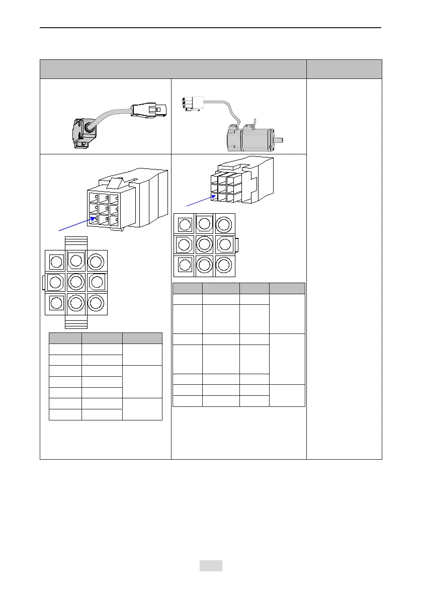
Table 4-12 Connectors of IS810N series absolute encoder cables (9-pin connector)
Connector Appearance and Pin Layout
Frame Size of
Applicable Motor
Encoder cable
connector
Connect
to CN2 of
the drive
40
60
80
9-pin connector
Pin No. Signal Remarks
1 Battery +
-
4 Battery -
3 PS+
Twisted-
pair
6 PS-
9 +5 V
8 GND
-
7 Shield
Recommendation:
Plastic housing: AMP 172161-1;
Terminal: AMP 770835-1
Pin No. Signal Color Remarks
A PS+ Yellow
-
B PS-
Yellow
and
black
E Battery + Blue
Twisted-
pair
F Battery -
Blue
and
black
G +5 V Red
H GND Black
-
J Shield
Frame size of motor: indicates the width of the installation ange.
 Loading...