Micromate Operator Manual – 721U0201 Revision 6 117
parts list in the appendix for standard extension cable lengths and part numbers.
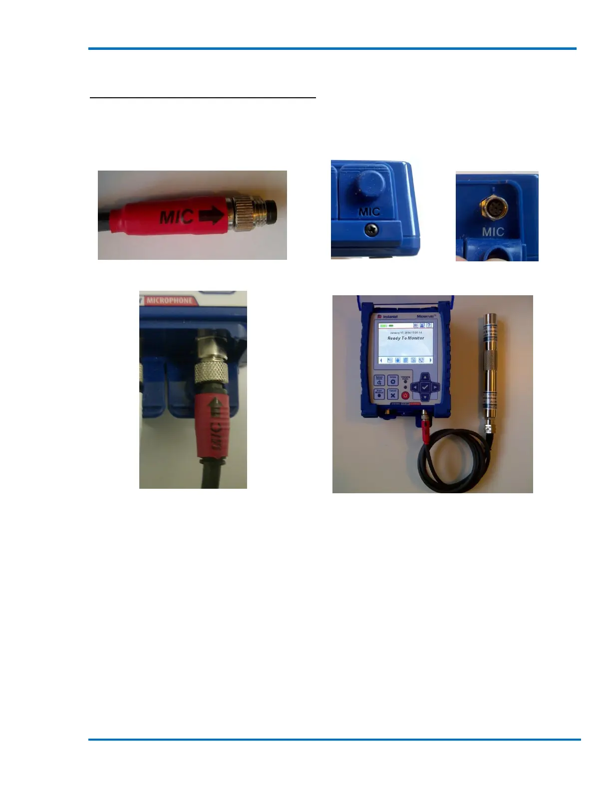
Connecting Linear Microphone to Micromate:
The microphone cable connector has a red “MIC” label with an arrow indicating how the connector
will mate with the connector on the Micromate unit. The dust cap and connector on the
Micromate is also labeled as “MIC”. The microphone port is also labeled and color coded red on
the keypad above the microphone connector.
Microphone Cable Connector Microphone Dust Cap Microphone Connector
Microphone Connected to the Micromate
14.4. Installing the Linear Microphone
The microphone installation procedures are based on ISEE field practice guidelines for blasting
seismographs (2009 Edition). This section illustrates the installation procedures recommended by
Instantel. Your particular monitoring activities may employ one, or a combination of all, of the
following procedures.
14.4.1. Soft Material Installations
The linear microphone is supplied with a three piece microphone stand. The top section has a clip
to hold the microphone, the extension section is threaded at both ends and the bottom Section is
pointed to assist in the installation. When the three pieces are assembled the microphone stand is
approximately 0.8 meters (33 inches) tall. If the air overpressure is to be monitored at a height