5. Tighten the capve screws on the faceplate of the fan module by using your ngers. If you are unable
to ghten the capve screws by using your ngers, use the screwdriver.
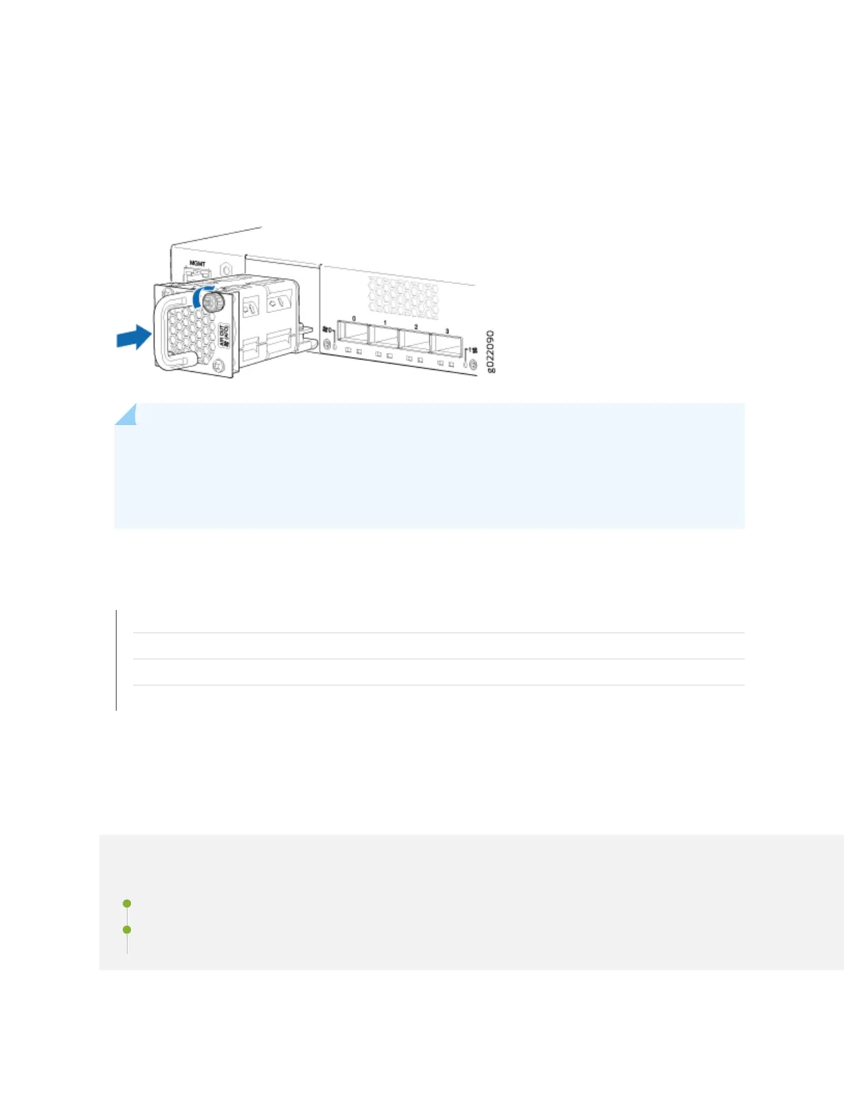
Figure 87: Installing a Fan Module in a 24-Port EX4300 Switch
NOTE: If you have a Juniper J-Care service contract, register any addion, change, or upgrade of
hardware components at hps://www.juniper.net/customers/support/tools/updateinstallbase/ .
Failure to do so can result in signicant delays if you need replacement parts. This note does not
apply if you replace exisng components with the same type of component.
SEE ALSO
Removing a Fan Module from an EX4300 Switch | 292
Cooling System and Airow in an EX4300 Switch | 82
Field-Replaceable Units in EX4300 Switches | 52
EX4300 Switches Hardware Overview | 2
Maintaining the EX4300 Power System
IN THIS SECTION
Removing an AC Power Supply from an EX4300 Switch | 296
Installing an AC Power Supply in an EX4300 Switch | 298
295