NOTE: The procedure is the same for EX4300-48MP and EX4300-48MP-S switches.
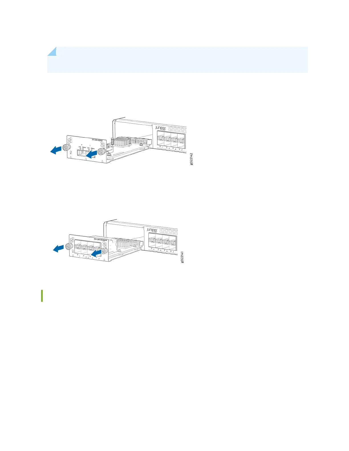
Figure 93: Removing a 2-Port 40-Gigabit Ethernet QSFP+ Uplink Module from a 32-Port EX4300
Switch
Figure 94: Removing an 8-Port 10-Gigabit Ethernet SFP+ Uplink Module from a 32-Port EX4300
Switch
Installing an Uplink Module in an EX4300 Switch
Before you begin installing an uplink module in the switch:
• Ensure that you have taken the necessary precauons to prevent ESD damage (see
Prevenon of
Electrostac Discharge Damage
).
Ensure that you have the following parts and tools available:
• Electrostac discharge (ESD) grounding strap (If a grounding strap is not available, follow the
alternave grounding method described in Step 1 of the following procedure.)
• Phillips (+) screwdriver, number 2
306

 Loading...


