NOTE
Tighten each screw terminal to the correct torque. The tightening torque is marked
on the terminal block.
Connect L1, L2, L3, N and PE to the correct terminal blocks:
• Connection to charging socket/vehicle connector 1 to the terminal
blocks labelled L1, L2, …
• Connection to charging socket/vehicle connector 2 to the terminal
blocks labelled L1.2, L2.2, …
• PE wire to the terminal block on the DIN rail. Do not connect the PE wire
to the front panel of the unit.
If the site has multiple AC Satellites, we recommend shifting the phase
order L1→L2.2 | L2→L3.2 | L3→1.2 to balance the power consumption in the grid.
In the AC Satellite with charging cables:
• Route each charging cable through the residual current monitor (RCM)
before you connect it to the contactor (K4, K5).
• Connect only the white CP signal wire of the charging cable to the unit
connector (X4 right, X5 left).
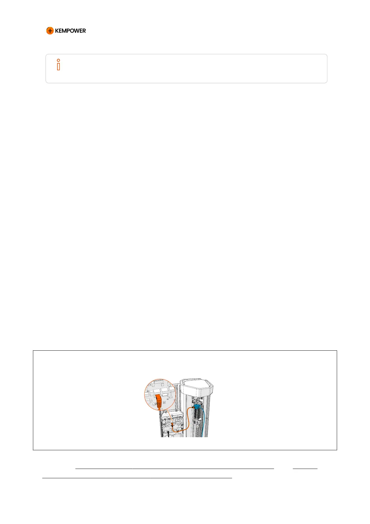
If the optional Ethernet cable is used:
1. Install the Ethernet terminal block to the top of the DIN rail.
2. Connect the Ethernet cable between the control board and the
terminal block.
3. Connect the site network Ethernet cable to the other side of the
terminal block.
Figure 47. Connecting the AC Satellite Ethernet cable
See also 11.11: AC Satellite Version 2 with two vehicle connectors and 5.2.14.1:
Terminal blocks (AC Satellite with charging cables).
CHARGING EQUIPMENT FOR ELECTRIC VEHICLES INSTALLATION MANUAL
CONFIDENTIAL – CERTIFIED PARTNERS 103 REV 2.40 EN 04-2024