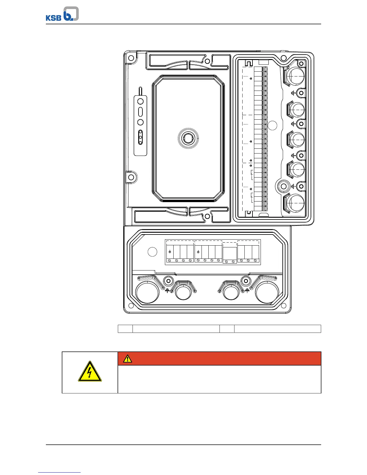
EasyManua.ls Logo

KSB PumpDrive 2 - Page 40

KSB PumpDrive 2
212 pages
Print Icon
To Next Page IconTo Next Page
To Previous Page IconTo Previous Page
Loading...
7 Installation at Site
40 of 212
PumpDrive 2
7.4.3.2 Overview of terminal strips
L1 L2 L3
LINE
PE U V W
MOTOR
1
2
C1
C2
C3
C4
C5
C6
C7
C8
C9
C10
B1
B2
B3
B4
B5
B6
B7
B8
B9
B10
A1
A2
A3
A4
A5
A6
A7
A8
A9
A10
DI-EN
+24V
GND
DI4
DI3
DI2
DI1
+24V
DICOM1
DI5
AO1-GND
AO1
AIN2 +
+24V
AIN1 +
+24V
GND
GND
COM2
NO2
COM1
NC2
+24V
GND
+24V
AIN2 -
AIN1 -
GND
NC1
NO1
P TC
MOTOR
PE
+ BR -
Fig.20: Overview of terminal strips
1 Mains and motor connection 2 Control cables
7.4.3.3 Connecting mains and motor
DANGER
Touching or removing the terminals and connectors of the braking resistor
Risk of fatal injury due to electric shock!
Never open or touch the terminals and connectors of the braking resistor.

Table of Contents

Other manuals for KSB PumpDrive 2

Related product manuals