7 Installation at Site
41 of 212
PumpDrive 2
CAUTION
Incorrect electrical installation
Damage to the frequency inverter!
▷ Never fit a contactor (in the motor connection cable) between the motor and
the frequency inverter.
1. Route the mains or motor connection cables through the cable glands and
connect to the specified terminals.
2. Connect the line for a PTC connection/PTC thermistor to the PTC terminal strip
(3).
NOTE
In the event of a short circuit in the winding (short circuit between phase and PTC),
a fuse trips and prevents carryover of low voltages to the low-voltage level. In the
case of a fault or malfunction, this fuse can only be replaced by KSB service
personnel.
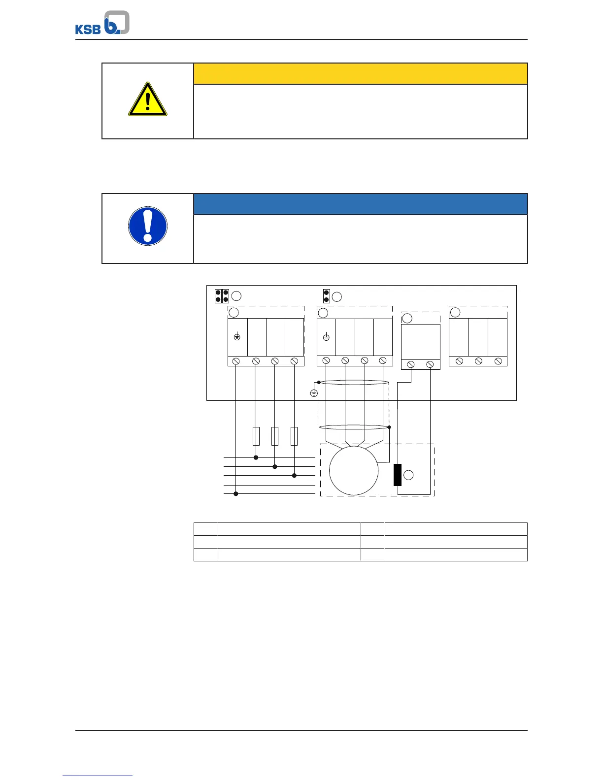
Size A
Fig.21: Establishing the power supply and motor connections, size A
① Mains connection ② Motor connection
③ PTC connection ④ Braking resistor
⑤ Motor PTC ⑥ Jumper for IT mains